Tripod Quick Release Mount Installation for the Focus Laser Scanner
Overview
The FARO® Laser Scanner Quick Release allows you to easily attach and detach the laser scanner from your tripod. Using the steps in this article you can install the quick release components to the scanner and tripod. Different models have been produced by FARO, refer to the section below that matches your unit.
Tripod Quick Release Mount (ACCSS8031)
Gather Parts & Tools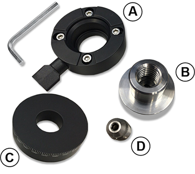
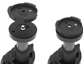
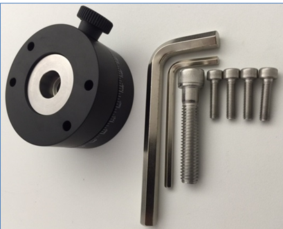
The Quick Release Package (FARO Part #: ACCSS8031) comes with the following components.
- 1 x Part A - Scanner Mount (Focus)
- 1 x Part B - Coupling (with int. 5/8” thread)
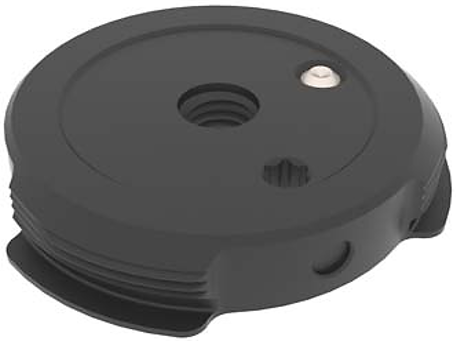
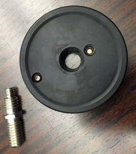
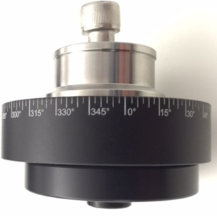
- 1 x Part C - Base Plate w/Graduated Dial
- 1 x Part D - Thread Adapter 5/8” to 3/8” (shipped pre-installed into Part B)
- 1 x Hex Key (4 mm)
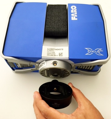
Attach the Scanner Mount to the Bottom of the Scanner
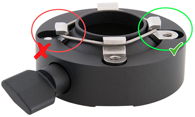
- Verify that all four hooks on the Scanner Mount (A) are in their fully retracted position. If necessary, using the provided hex key, loosen the screws until the hooks are in the correct position as shown below.
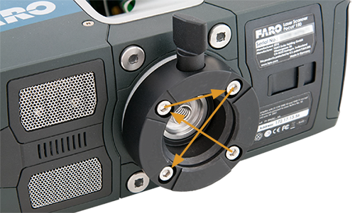
- Position the Scanner Mount (A) on the base of the Laser Scanner as shown. Using the provided 4mm hex key tighten the four screws in a criss-cross pattern as shown. Continue tightening in this pattern until all screws are snug, do not exceed 1.5Nm (13in-lb).
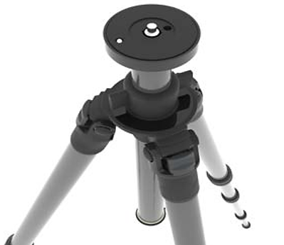
Set Up the Tripod
- Extend the legs of the tripod and lock the leg angle clips.
- Ensure that the tripod is stable, the feet are secure, and the platform is as level as possible.
- Remove any previously installed adapters or mounting plates.
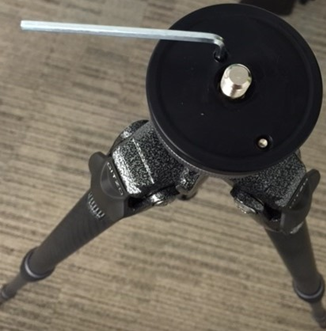
Attach the Base Plate to the Tripod Platform
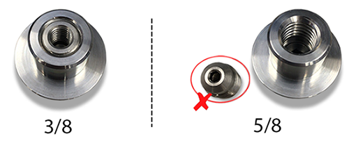
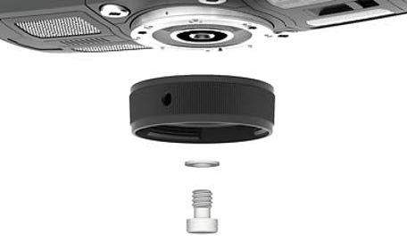
- Verify the mounting stud of the tripod is a 3/8 thread. If the mounting stud is a 5/8 thread, the Thread Adapter (D) should be removed from the Coupling (B) using the provided 4mm hex key.
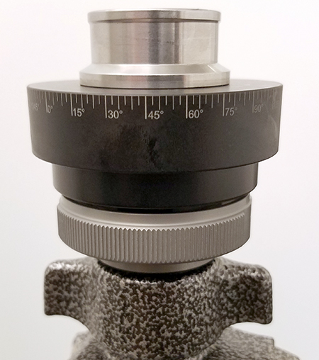
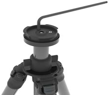
- Place and center the Base Plate w/Graduated Dial (C) onto the tripod platform.
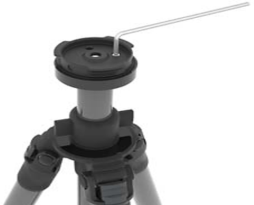
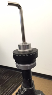
- Thread the Coupling (B) onto the tripod threaded stud and tighten firmly using a 5/16 or 8mm hex key (not provided).
- Check that the base plate is securely attached to the tripod platform.
Attach Base Plate to Tripod (ACCSS8032)
- Before attaching the mount to the tripod baseplate, remove the protective covering from the tripod baseplate screw.
- Attach the mount in the same manner as depicted above.
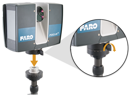
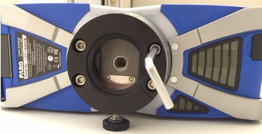
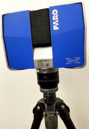
Install the Scanner Onto the Tripod
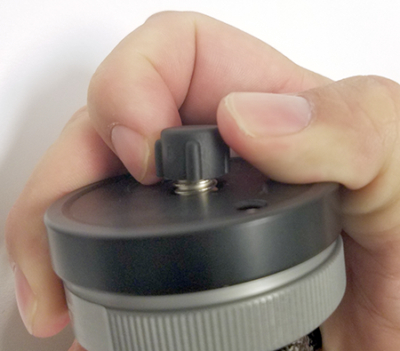
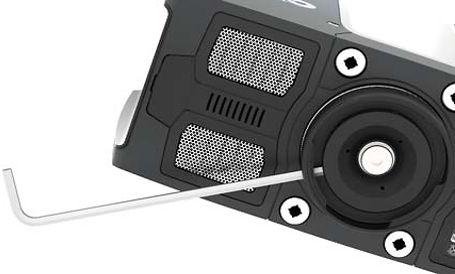
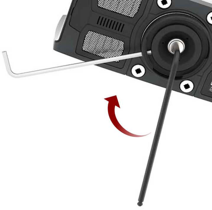
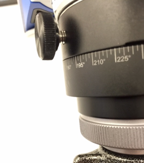
- Ensure the thumbscrew is loosened enough so that it does not interfere with the mounting of the scanner.
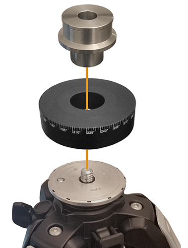
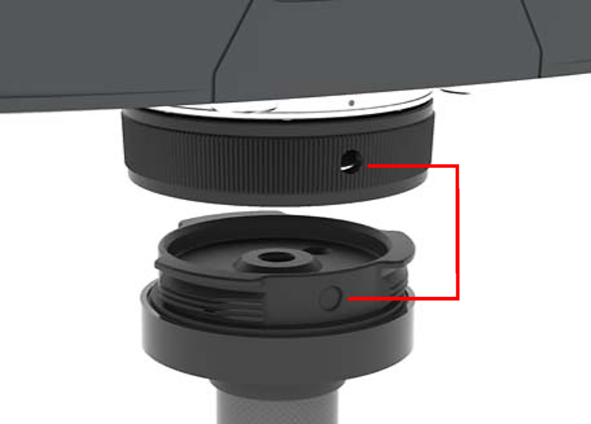
- Holding the scanner above the tripod, lower the scanner onto the tripod over the Coupling (B).
- Rotate the scanner to orient it relative to the location you want to scan.
- Tighten the thumbscrew until the scanner is securely locked onto the tripod.
- Check that the scanner and tripod are correctly locked gently lifting up on the bottom of the scanner. If it stays attached to the tripod the scanner is secure.
- Check the inclinometer and adjust your tripod to make sure it is secure and level before you begin your scan project.
Additional Tips
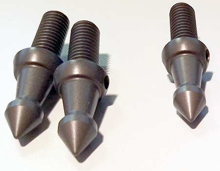
- If you are setting up the tripod on a natural surface, replace the rubber tripod feet with spikes for increased stability.
- Periodically check the tightness of the quick release on the tripod.
- Never force the laser scanner to turn without releasing the thumb screw.
- Remove the laser scanner before moving the tripod.
To Achieve Stability and Rigidity
- Extend the tripod as little as possible. Less height means more accuracy.
- Extend the thicker segments of the legs before the thinner.
- You can extend a leg segment partially, if necessary, to achieve a specific height, but do not partially extend several segments of the same leg.
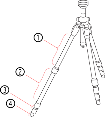
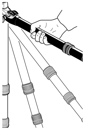
- The tripod has four leg segments, three of which are extendable. Fully extend segment ②, leaving segments ③ and ④ collapsed. This results in a working height of approximately 130 cm (51.2 in).
- The tripod is equipped with large, adjustable rubber feet. Each time you move the tripod, ensure that the feet are correctly resting on the ground. If you need to place the tripod on unstable ground (e.g., grass, gravel, mud), use the supplied spikes instead of the rubber feet. Press the spikes individually into the ground until they reach a stable, load-bearing layer.
- After you set the tripod on the ground, check the leg latches. If any latches are loose, spread the legs slightly until the latches cannot be wiggled. This ensures that the tripod is firmly planted on the ground, and unlikely to shake or vibrate during scanning.
- The use of the center column significantly reduces the rigidity of the tripod. We recommend that you avoid using the center column. If you need higher working heights, we recommend using a larger tripod. Make sure that a such a tripod is also stable.
- For scans close to the ground, slide all leg segments into each other before setting the leg angle to flat. The rubber feet have a recess that helps to achieve full-surface contact, even with a flat leg angle. To do this, turn the feet individually by hand.
- Ensure that the twist-lock sleeves for leg length adjustment, the central wing nut of the tripod shoulder, and the tripod head are always tightly screwed together.
- To achieve a better grip on hard surfaces, slightly tension the tripod legs before starting a scan. Tension the legs by holding two of the three tripod legs as close to the ground as possible with your hands, pulling them slightly apart from each other and away from the third leg, then pressing them into the ground.
Windy Conditions
FARO recommends the use of the ACCSS8032 tripod (with the Focus scanner) in winds less than 35mph (56km/h). In stronger winds, it may be required to use a heavier aftermarket surveyor type tripod. See the following guidelines to maximize stability of your FARO tripod in windy conditions.
- Use sandbags to stabilize each foot of the tripod. You can also stretch a rope or shock cord between the tripod’s center hook and a weight (max. 20kg), switchable magnetic base, or existing anchor point (max. force 200N).
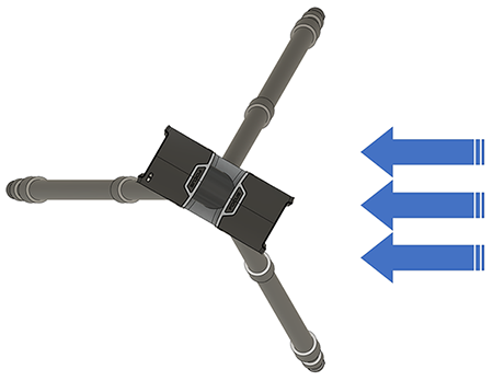
- Orient one of the tripod legs with the main wind direction. Also, only extend one section of the tripod legs (never extend the center column – this degrades the resistance against vibrations).
- Tripod legs must be opened to the side at the maximum in first horizontal lock position. It’s possible to lock the legs in wider horizontal position but this will dramatically limit the scanner height and make the setup less resistant against vibration.
Tripod Quick Release Mount (ACCSS8008) - Obsolete
Prepare
Gather Parts & Tools
- Order the Quick Release Package from FARO® Sales.
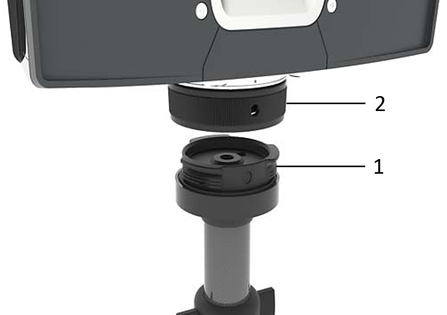
Laser Scanner Quick Release package—FARO Part #: ACCSS8008 - When you receive the package, verify you have these parts.
- 1 Base Plate attaches to the tripod platform (item 1 in the picture)
- 1 Mount Plate attaches under the scanner (item 2 in the picture)
Note: Part a and b are attached together when you receive the package. Rotate the Mount Plate to separate the two parts.
- 1 Imperial 3/16" Hex Key (depicted in these pictures as black in color)
- 1 Metric 3 mm Hex Key (depicted n these picture as silver in color)
- Retrieve the Tripod Hex Key from the original package.
Set Up the Tripod
- Extend the legs of the tripod and lock the leg angle clips.
- Ensure that the tripod is stable, the feet are secure, and the platform is as level as possible.
- Make adjustments as needed to the platform set screws (one or more) using the original tripod hex key to recess the screws below the platform surface. For correct installation of the base plate, they must not extend above the platform surface.
Attach the Base Plate to the Tripod Platform
- Ensure that the base plate set screw is recessed below the surface of the base plate by inserting the 3 mm silver hex key into the hexagonal recess in the center of the set screw.
- Install the base plate on the tripod platform by threading the base plate 3/8" center hole onto the tripod platform 3/8" threaded stud. The two parts should fit flush against each other. Twist the base plate in a clockwise direction, securing it snuggly to the platform.
- Firmly tighten the base plate to the platform using the 3/16" black hex key inserted into the hexagonal recess on the base plate.
- Tighten the base plate set screw using the 3 mm silver hex key inserted into the recess at the center of the set screw.
- Check that the base plate is securely attached to the tripod platform and is unable to spin in any direction.
Attach the Mount Plate Under the Scanner
- Attach the mount plate beneath the scanner using the central 3/8" screw, tightened with your fingers so it is snug but not firmly tightened.
- Insert the long end of the 3 mm silver hex key into one of the three openings on the side of the mount plate outer ring. With the key inserted, slightly rotate the outer ring to find a spot where the key easily seats into one of the six hexagonal holes of the mount plate inner ring. Ensure that the key has engaged completely with the hole in the inner ring.
- Insert the short end of the 3/16" black hex key into the hexagonal recess in the central 3/8" threaded screw on the mount plate.
- Holding the silver key firmly in the hole in the inner ring, tighten the central 3/8" screw with the black key. Do not let the silver key have any leverage while you are tighten the central screw.
- Check that the mount plate is securely attached to the scanner and does not move in any direction
Lock the Scanner Onto the Tripod
- Holding the scanner above the tripod, align one of the three lock holes on the scanner mount plate outer ring with a corresponding circular indentation on the side of the tripod base plate.
- Lower the scanner onto the base plate keeping the lock hole aligned with the corresponding circular indentation..
- With the scanner contacting the base plate, turn the scanner to orient it relative to the location you want to scan.
- On the scanner mount plate, rotate the outer ring until the scanner is securely locked onto the tripod.
- Check that the scanner and tripod are correctly locked gently lifting up on the bottom of the scanner. If it stays attached to the tripod the scanner is secure.
- Check the inclinometer and adjust your tripod to make sure it is secure before you begin your scan project.
To Achieve Stability and Rigidity
- Extend the tripod as little as possible. Less height means more accuracy.
- Extend the thicker segments of the legs before the thinner.
- You can extend a leg segment partially, if necessary, to achieve a specific height, but do not partially extend several segments of the same leg.
- The tripod has four leg segments, three of which are extendable. Fully extend segment ②, leaving segments ③ and ④ collapsed. This results in a working height of approximately 130 cm (51.2 in).
- The tripod is equipped with large, adjustable rubber feet. Each time you move the tripod, ensure that the feet are correctly resting on the ground. If you need to place the tripod on unstable ground (e.g., grass, gravel, mud), use the supplied spikes instead of the rubber feet. Press the spikes individually into the ground until they reach a stable, load-bearing layer.
- After you set the tripod on the ground, check the leg latches. If any latches are loose, spread the legs slightly until the latches cannot be wiggled. This ensures that the tripod is firmly planted on the ground, and unlikely to shake or vibrate during scanning.
- The use of the center column significantly reduces the rigidity of the tripod. We recommend that you avoid using the center column. If you need higher working heights, we recommend using a larger tripod. Make sure that a such a tripod is also stable.
- For scans close to the ground, slide all leg segments into each other before setting the leg angle to flat. The rubber feet have a recess that helps to achieve full-surface contact, even with a flat leg angle. To do this, turn the feet individually by hand.
- Ensure that the twist-lock sleeves for leg length adjustment, the central wing nut of the tripod shoulder, and the tripod head are always tightly screwed together.
- To achieve a better grip on hard surfaces, slightly tension the tripod legs before starting a scan. Tension the legs by holding two of the three tripod legs as close to the ground as possible with your hands, pulling them slightly apart from each other and away from the third leg, then pressing them into the ground.
- Under windy conditions, use sandbags to stabilize each foot of the tripod. You can also stretch a rope or shock cord between the tripod’s center hook and a weight, switchable magnetic base, or existing anchor point.
Troubleshooting
When attempting the remove the scanner from the tripod, in some instances the entire quick release assembly can begin to rotate making it impossible to separate the two quick release halves. If this occurs:
- Continue rotating the outer ring clockwise (to the right) until the scanner and the complete quick release assembly is free of the tripod.
- Set the scanner upside down on a sturdy surface. Insert the 3/16 hex key into the hex socket (A) of the base plate (B). While firmly holding the knurled outer ring of the mount plate (C), rotate the 3/16 hex key in a counter-clockwise direction to separate the base plate from the mount plate.
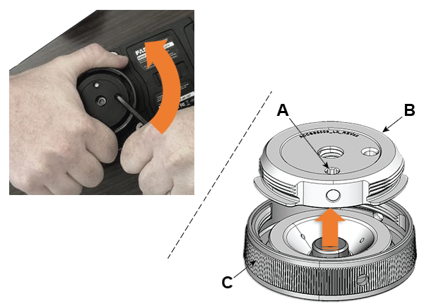
- Once separated, reinstall the base plate per the steps in the above section, Attach the Base Plate to the Tripod Platform. When reinstalling, be sure the base plate is firmly tightened to the platform of the tripod (Step3) and then firmly tighten the set screw (Step 4).
Tripod Quick Release Mount (ACCSS6040) - Obsolete
Video
In this 3-minute video tutorial, learn how to unpack and set up the FARO Focus3D Laser Scanner on the panorama tripod.
Prepare
Setup
- Verify you have these parts in your Panorama Tripod Quick Release package.
- 1 x Mount assembly (two black components and integrated precision washer with knob)
- 1 x Screw (UNC 3/8x2”)
- 4 x Hex Screws (M5x20)
- 1 x Hex key 4mm
- 1 x Hex key 5/16”
- Optional: 1 x Tribrach to 5/8” adapter
- Remove the scanner from the transport case and lay the scanner on its side on a flat surface.
If you have a scanner transport cover, you can install the Tribrach adapter with the scanner inside the cover. Just lay the cover, with the scanner inside, on its side on a flat surface.
- Place the upper scanner mounting ring on the bottom of the scanner mount so that the four screw holes are aligned. Make sure that the set screw hole is opposite the power inlet.
- Insert and tighten the four screws with the included hex wrench; do not over tighten.
- To install the lower tripod mounting ring, first remove the 5/8-inch screw from the tripod using reasonable torque.
- This allows you to remove the 5/8” thread that you will set aside.
- Re-attach the black piece (pictured above) to the tripod with the lower portion of the quick release. Insert the 5/8-inch screw and tighten until snug with the included hex wrench. Make sure that the numbers on the tripod mounting ring are right-side up.
- Once the tripod mounting ring is secure, place the scanner on the tripod.
- Tighten the set screw to secure the scanner mounting ring to the tripod mounting ring.
Next Steps
Once you have confirmed the Tribrach adapter is attached and secure on the tripod, you are ready to use the quick release with your tripod and Focus3D.
Troubleshooting
If you cannot remove the screw in steps 5 and 6, do not apply excessive force as it may damage the tripod. Instead, contact FARO Support for instructions.