Compensating the Laser Line Probe (LLP) Using USB FaroArm Driver 6.1.0 and Later
Overview
To make sure your project has the most accurate measurement results, always compensate (sometimes referred to as calibrate) your LLP before starting a measurement project.
The 6.0 and later versions of the FaroArm driver include the FaroArm Manager which enables you to compensate your device after connecting it to a PC with the driver installed.
- Click here to check the version number of the driver installed on your PC. If the version number is 6.1.0 or later, use these instructions. If not, click here for earlier instructions.
- Download the latest FaroArm Manual for additional compensation instructions.
Refer to the video for below for simple compensation instructions.
Video
In this video, see the complete routine for compensating the FARO Laser Line Probe (LLP).
Tips
Look for these highlights as you watch the video demonstration above.
- Before using the calibration/compensation plate, assure the underside of the plate and the surface it will be placed on, are clean and free of any debris. The flatness specification for the white surface of the plate is 0.001” (0.0254mm). This dimension is not a traceable specification and is not verified during the certification process.
- The operator takes a series of 5 strokes covering 4 positions of the compensation plate while moving the LLP far from and near to the plate.
- As he orients and takes each stroke, watch the indicators on the right-side of the Compensation panel of the FaroArm Manager software (see the Steps section below for details). The operator keeps all the indicators in the green color range as much as he can.
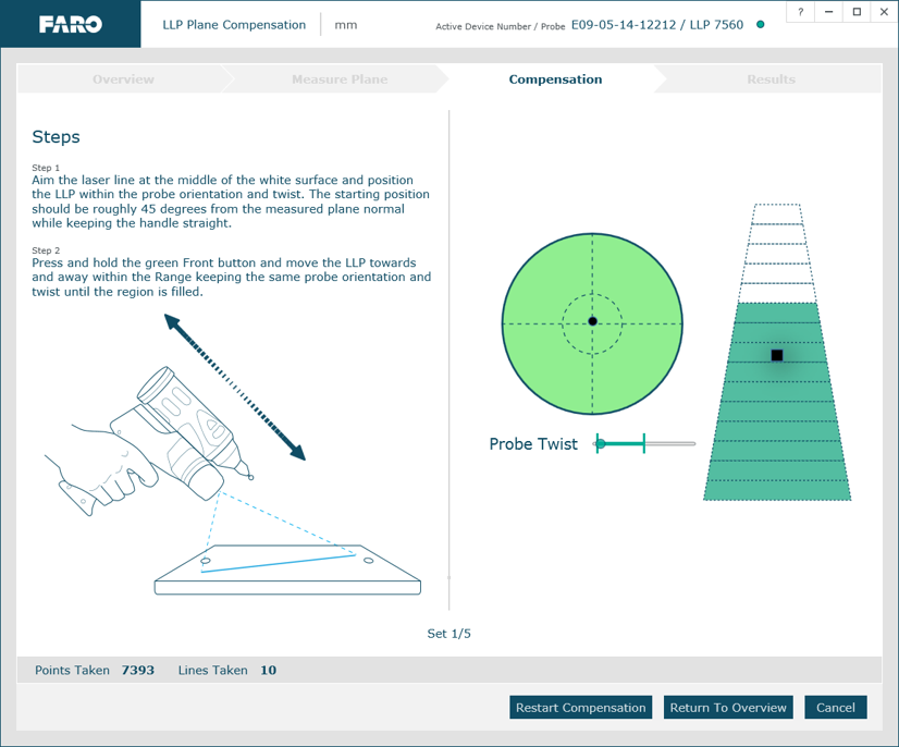
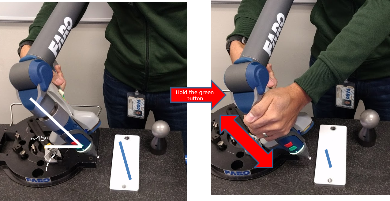
- The circular Radar indictor assesses the orientation and angle of the LLP to the plate. Try to keep the angle at about 45°. Green means the LLP is correctly angled and oriented. Other colors mean the operator must correct the angle or orientation of the LLP.
- The Probe Twist indicator assesses if the LLP handle is twisting as you make your stroke. Green means it is not twisting. Other colors mean the operator must hold the handle steady.
- The Trapezoid indicator assesses the coverage and completeness of the stroke. As long as the Radar and the Probe Twist indicators are green, the operator can completely fill the Trapezoid with green bars from bottom to top. This means the strokes are correct. Other colors mean the operator must adjust the stroke angle and twist, as well as coverage of the plate. To cover the plate, the operator must keep the laser line on the plate while he makes the stroke.
- It does not matter if the operator's strokes start far from the plate or near it, as long as all indicators are in the green and the Trapezoid indicator is completely filled.
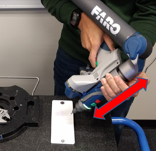
- As the operator makes the stroke from far to near, or the reverse, he keeps the LLP laser beam stationary and on the plate.
- For best results, the operator keeps the black dot on the Radar indictor as close to the center as best he can.
Steps
Refer to the video above for the compensation procedure as you walk through the steps. Download the latest FaroArm Manual and additional compensation information.
Compensation Setup
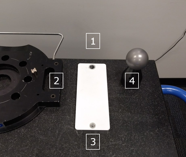
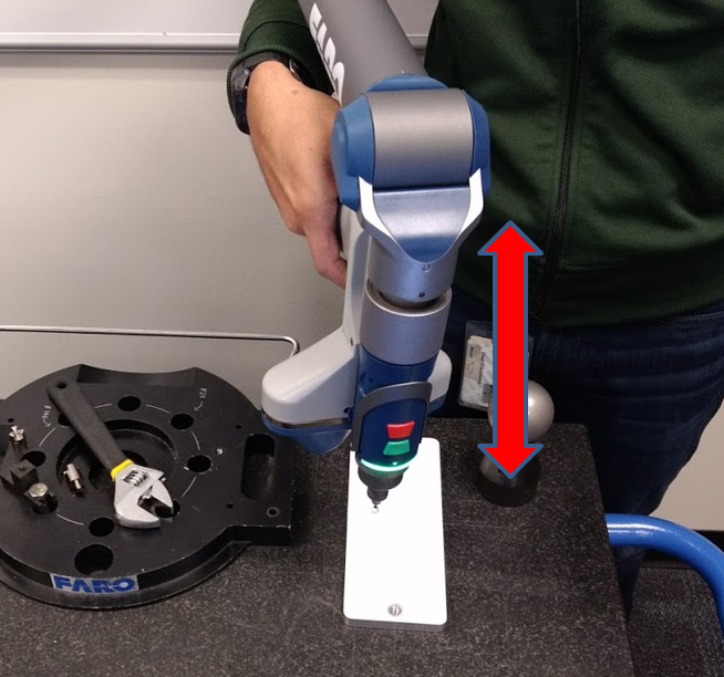
- Place the compensation plate long-ways to the surface of the work table and stand behind the table at position 1, as shown in this image.
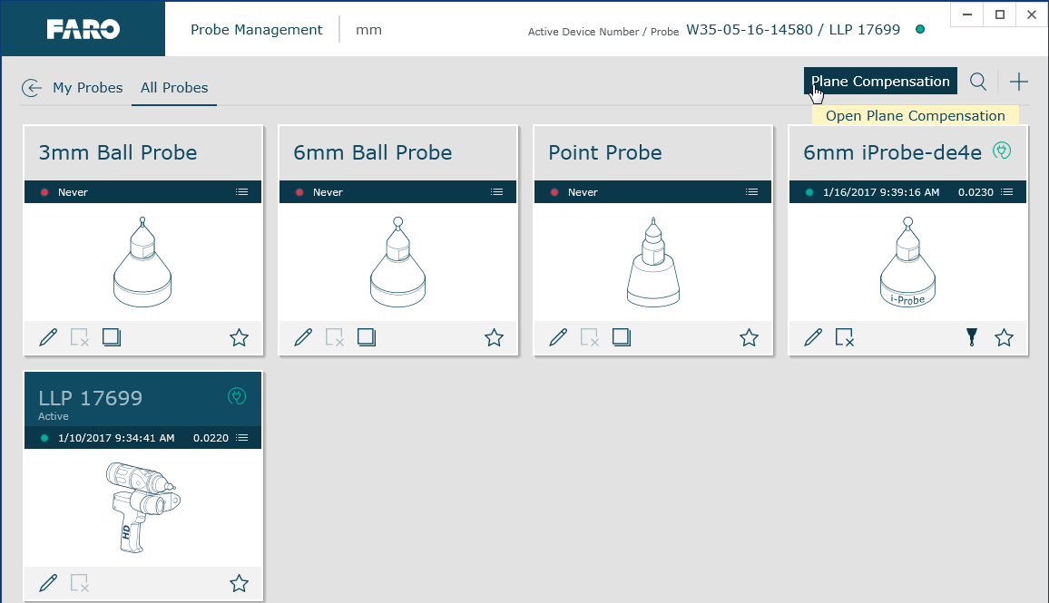
- Turn on the FaroArm and connect it to a computer running the FaroArm driver version 6.1 or later. From the Windows Start Menu click FARO > FaroArm Manager > Probe Management. The Probe Management panel appears.
- Click on the type of hard probe that is attached to the FaroArm and compensate the hard probe using the Hole Compensation method. If you do not know how to do this, download the latest FaroArm Manual and in the Search field type Probe Management.
- After the hard probe is compensated, in the Probe Management panel, click Laser Line Probe to activate it. Then, in the top-right corner, click Plane Compensation. The Overview Compensation panel appears.
- Then, click Measure Plane to measure the compensation plate as a plane, using at least 8 points. If you do not know how to do this, download the latest FaroArm Manual and in the Search field type Laser Line Probe Compensation. When the Success indicator appears, click Start Compensation. The Compensation panel appears
Compensation
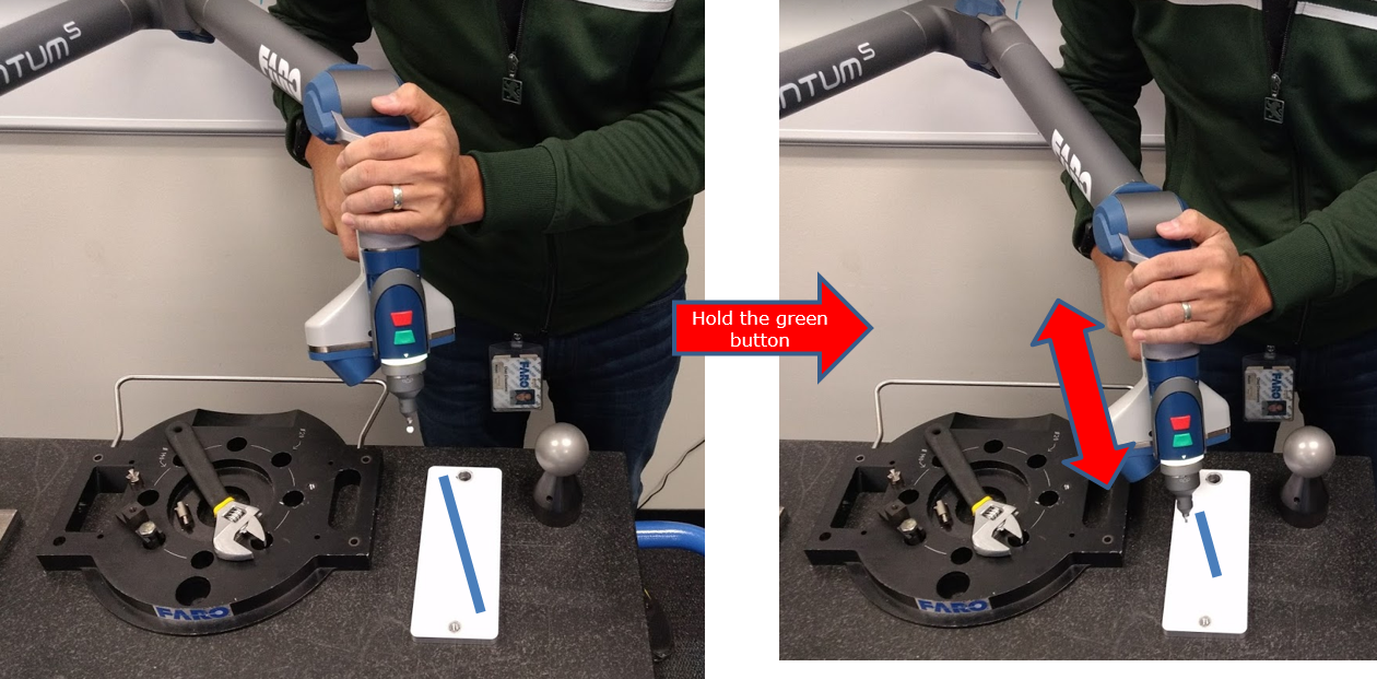
- To cover position 1 on the plate, start the stroke with the LLP oriented perpendicular to the plate and aim the laser lines directly at the center of the plate. In the Compensation panel, the Radar indicator should show a black dot at the center. If not, move the LLP until the dot centers.
- Tilt the LLP 45° towards you and hold the green button to collect data. Move the LLP far from the plate and near to it until the Trapezoid is filled with green bars. Remember to watch the Radar indicator in the Compensation panel while you move the LLP to keep the black dot at the center and the other indicators in the green. Keep the laser lines on the plate at all times. When the Trapezoid indicator is filled, release the green button and proceed.
- To cover position 2 and start the stroke, return the LLP to perpendicular, aligning the black dot at the center of the Radar and keeping all the indicators in the green. Tilt the LLP 45° to the right and hold the green button to collect data. Move the LLP far from the plate and near to it until the Trapezoid is filled with green bars. Watch the Radar indicator, keep the black dot at the center, and all indicators in the green. When the Trapezoid is filled, release the green button and proceed.
- To cover position 3 and start the stroke, move the LLP towards the bottom of the plate. Return the LLP to perpendicular, aligning the black dot at the center of the Radar and keep all indicators green. Tilt the LLP 45° away from you and hold the green button to collect data. Move the LLP far from and near to the plate until the Trapezoid is filled with green bars. Watch the indicators. When the Trapezoid is filled, release the green button and proceed.
- To cover position 4 and start the stroke, return the LLP to perpendicular, aligning the black dot at the center of the Radar and keep all indicators in the green. Tilt the LLP 45° to the left and hold the green button to collect data. Move the LLP far from and near to the plate until the Trapezoid is filled with green bars. Watch the indicators. When the Trapezoid is filled, release the green button and proceed.
- For the final 5th stroke, return the LLP to perpendicular and aim the laser lines directly at the center of the plate. The Radar indicator should show a black dot at the center. Hold the green button. Move the LLP far from and near to the plate it until the Trapezoid is filled with green bars. Watch the indicators. When the Trapezoid is filled, release the green button and the result will be displayed. The compensation is complete.
- The FaroArm Manager calculates the compensations points. When it is done, the Results panel appears, displaying the success Status, as well as Error and Specification metrics. Click Save and Exit.
- Compensation is complete
See Also
- User Manual for the Quantum Series FaroArm and ScanArm
- Compensation, Calibration, and Certification Standards for FARO Devices
Keywords:
scanarm, scanner, calibrate, calibration, llp calibration, laser line probe calibration, llp settings, laser compensation, compensate, compensation