On-Site Compensation Instructions for the Focus S Series
Overview
The On-Site Compensation process is a procedure to test and improve the angular accuracy of the scanner using SCENE software. Note: On-Site Compensation is only available on FocusS models.
Site Setup
Before you begin the On-Site Compensation process, ensure that the scan site has the following facilities:
- Select a room / area without movements or the presence of other people during the On-Site compensation (OSC) process.
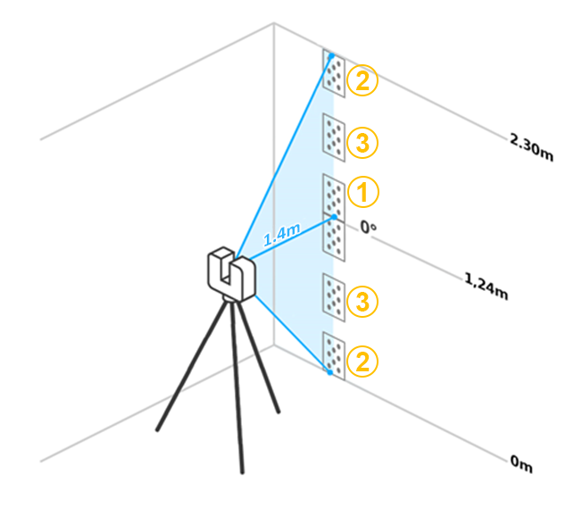
- Target sheets must be setup at the scan site at a regular distance to the laser scanners of about 1.4m (4.5ft).
- A minimum room height of 2.3m (7.5ft) is required.
- No windows or other reflective planes: The markers on the target sheets would be reflected if the scan site has any windows or reflective surfaces. This can cause incorrect measurements.
- Lighting conditions are less important because On-Site Compensation (OSC) is done with the laser, video images are not used.
Printing Target Sheets
If you need compensation target sheets, you can download and print them or print them from SCENE
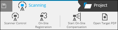
- Click the Scanning Ribbon.
- Click Open Target PDF.
- Print at least six copies of the PDF using the DIN/ISO A4 format or US letter format using the following guidelines:
- Targets should be printed using a laser printer, do not use ink jet printers.
- Print only on standard mate paper, do not use glossy/photo paper.
- Prints should be flat and free of folds or creases and should lay flat when attached to the wall.
- We recommend that you glue the target sheets onto a suitable rigid backer board, especially if compensation is done at an outdoor location or in locations with air movement.
Positioning the Laser Scanner and Target Sheets
- Using the FARO tripod (ACCSS8032) extend only the first sections (biggest tube diameter) on all 3 legs of the tripod.
- The center column should be fully retracted (lowest position). This will place the center of the scanner mirror at a height of about 1.24m (4ft).
- The tripod legs should be fully opened and stable.
- Place the scanner about 1.4m (4.5ft) from the wall.
- Make sure the tripod is placed on a stable, flat surface. The tripod must not move during scanning.
- Level the scanner via the built-in inclinometer.
|
① Two “center targets” should be symmetrically positioned around the scanner horizontal axis.
All target sheets must be vertically aligned. Avoid any moving person or object in the area while performing the On-Site Compensation scan. |
 |
Note: With SCENE 2021.1 and later, the On-site Compensation scan angle was reduced allowing for faster compensation, but you must take care to orient the scanner accurately towards the targets. This new implementation of on-site compensation requires FocusS and FocusS Plus scanners, Focus firmware 6.8 (and later) and SCENE 2021.1 (and later).
On-site Compensation
Compensate with SCENE according to the user's manual and execute scanning and correction.
- In SCENE, Connect your PC to your scanner.
- Click Start On-Site Compensation in the Scanning ribbon.
- Select an output folder to store compensation data.
- Enter the IP address of the laser scanner.
- You can find the IP address by tapping Manage > General Settings > WLAN > IP Address on the scanner user interface.
- Click Connect.
- Verify that the targets and scanner are positioned as described above. Click Place Targets.
- Click on Horizontal Alignment
- Wait until the scanner has stopped rotating. Open the quick release and align the scanner so it is parallel to the wall/targets. Once aligned, lock the quick release.
- Alignment can be best be achieved when "sighting" through the chassis of the scanner (at the height of the mirror). From this position the “Center Targets” must be visible above and below the mirror.
- Click Scan & Compensate.
- When the compensation is finished, the Compensation Report is displayed with the results of the compensation. Open the compensation report PDF by clicking the button Open Report.
- Log data is stored together with Compensate report. (About 300 Mb with all data). Most of the data is scan data. Be sure to erase it properly when compressing the disk capacity
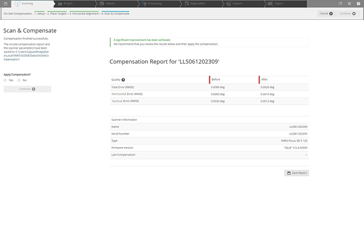
- To apply this compensation to the scanner choose Yes and click Finish. Choose No if you do not want to apply this compensation.
- You can then disconnect from the Scanner.
Troubleshooting
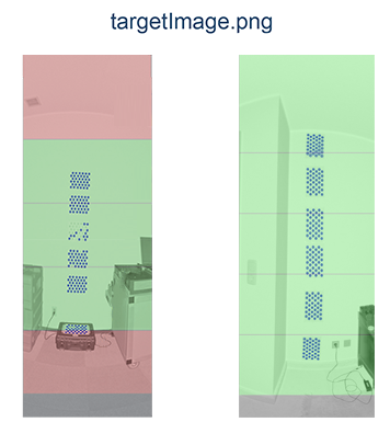
Error: The process did not identify enough targets for compensation.
- Solution: In the output folder a targetImage.png file is stored. This image shows the identified markers as blue circles. Areas with a sufficient amount of detected targets have a green background color. In case of an insufficient amount of detected targets the background color is red.
Error: Reading and writing to the selected data output folder failed.
- Solution: Make sure that you have permission to read and write in the selected output folder. Ensure that you have sufficient disk space. Approximately 330MB is necessary to perform an On-Site compensation.
Error: No consistent solution could be determined.
- Solution: Make sure that the tripod and the targets did not moving during the procedure.
Error: The SD card of the scanner could not be accessed.
- Solution: Make sure that the SD card is inserted and that it is not write-protected and has sufficient free space left (approximately 330MB).
Error: Communication with the scanner failed.
- Solution 1: Make sure that the WLAN connection to the scanner is stable. If this error appears when connecting to the scanner or applying the compensation parameters, try to repeat the corresponding step.
- Solution 2: With Focus Firmware earlier than 6.8, and using SCENE versions earlier than 2021.1, you may need to Enable SMB 1.0 protocol. Open “control panel” > “All control panel Items” > “Programs and Features” > “Turn Windows features on or off”. In the next window, search for “SMB 1.0” in the list. Tick the box, and activate this feature. Reboot your PC.
Keywords:
On-Site Compensation, Wireless connection, Wi-Fi, WLAN, Target