Pinout of the USB FaroArm Auxiliary Port Connector
USB FaroArm Auxiliary Port Schematic (Also known as the Base Option Port Schematic or 7th Variable Options Port)
Below is information for the USB FaroArm Auxiliary Port
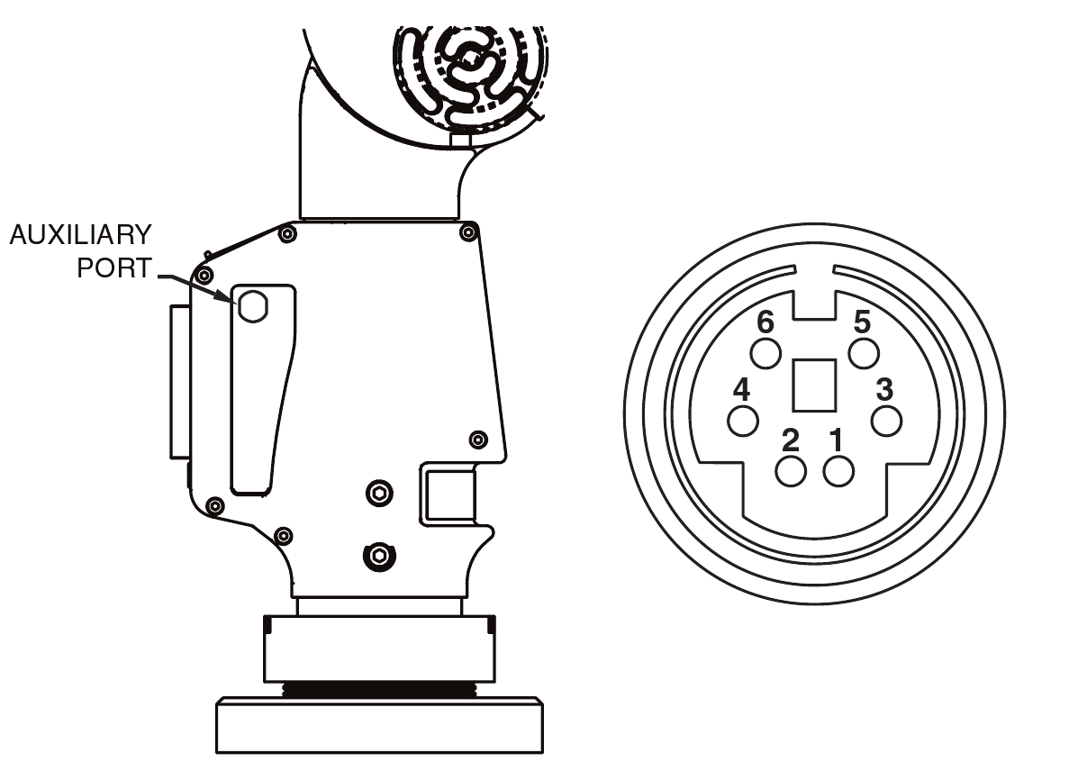
| Pin # | Signal Name | Description | Signal Direction | Comments |
| 1 | Trigger + | The Trigger signal is used to force the FaroArm to immediately issue a Capture signal. | From External interface to FaroArm. | RS485 differential signal. If (Pin 2 > Pin1 by 200mv) then the FaroArm will initiate a capture. |
| 2 | Trigger - | |||
| 3 | GND | Logic Ground | N/A | Connect to Ground |
| 4 | NC | No Connection | N/A | Do Not Connect |
| 5 | Capture + | The Capture signal acknowledges that a Trigger signal has been received and records the current position of the FaroArm. | From FaroArm to External interface. | RS485 differential signal. When (Pin 6 > Pin5 by 200mv) then the FaroArm has initiated a capture. |
Keywords: auxiliary, port, schematic Base Option Port Schematic Variable Options Port