Blood Spatter Analysis in FARO Zone 3D
Overview
This article provides instructions and tips for successful blood spatter analysis using FARO Zone 3D.
Visit the FARO Academy for a 40-minute video on how to utilize your crime scene photographs within the powerful blood spatter tool available in FARO Zone Expert.
Procedure
Success Starts at the Crime Scene
- Identify your patterns of interest.
- Label your bloodstain patterns for documentation:
- Grid large areas into smaller sections and make sure to label and document each one separately.
- OPTIONAL – If you are trained in BPA and wish to use individual stains for analysis, label each stain and utilize macrophotography to document them accordingly.
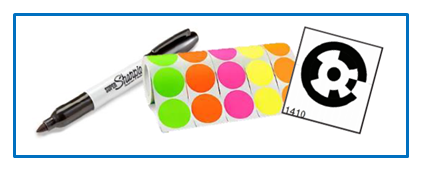
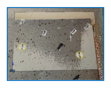
- Include some form of visible marker (sticker dots, coded markers, sharpie, sticker scales, etc.).
- The chosen type needs to be visible in BOTH the scan data AND photos for alignment.
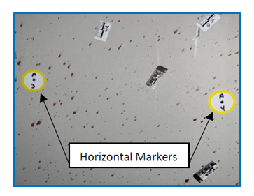
- Marker Placement:
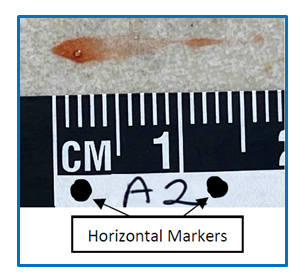
- For 2 point alignment - markers need to be placed on each side of the pattern of interest (horizontally).
- For 3 point alignment – an additional marker should be placed above or below the same pattern (I.e. two horizontal points, one vertical).
- Complete the following photographic documentation of selected patterns and/or individual stains.
- Overalls – standard photography rules apply.
- Mid-ranges – must be taken at 90 degrees if you are using the photo for analysis.
- A tripod is highly recommended along with the use of “Manual” or “Aperture” modes for focusing.
- Make sure to fill the frame with your markers visible at the pictures “borders”.
- OPTIONAL - Close ups (individual stains) – must be taken at 90 degrees if using for analysis.
- A tripod is STILL highly recommended along with the use of “Manual” or “Aperture” modes for focusing.
- Make sure to fill the frame and have your markers visible.
- Sharpie “dots” can be sufficient to act as markers:
- Scan IN COLOR not grayscale.
- Recommended settings: 1/4 resolution at 4x quality with the scanner positioned within 6ft of the pattern.
- Export the data from the scanner and import it into FARO SCENE.
- Process and register the scan data.
- Complete clean up as needed.
- Create a Project Point Cloud.
Blood Spatter Analysis in FARO Zone
- Import your Project Point Cloud
 .
.
- Pick your 0,0,0 point using the “center to pick point” option under cloud positioning tools
 .
. - Remove the roof/trees via the vertical cut off option (also under point cloud tools).
- Pick your 0,0,0 point using the “center to pick point” option under cloud positioning tools
- Create a new layer to work off of in the layer manager
 .
. - Open the Blood Spatter tool
 from the Power Tools tab.
 - Pick your alignment (2 point/3 point/etc).
- You can set a default alignment choice under Preferences
 .
.
- You can set a default alignment choice under Preferences
- Import the photo you wish to align to your point cloud.
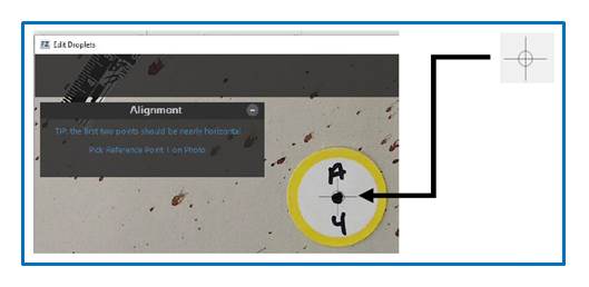
- Zoom in and pick your 2 (or 3) marker points on your selected photo (per your choice of alignment).
- Pick points by using the reticle on your curser to select the direct center of your chosen markers.
- When using marker “dots”, you can scroll in/out with your mouse to make the circle portion of the reticle match the size of the marker for easier selection.
- Pick the same 2 (or 3) points on the point cloud.
- Using the magnification window tool can help you zoom in on your point cloud when selecting points.
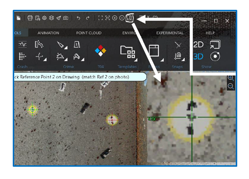
- Using the magnification window tool can help you zoom in on your point cloud when selecting points.
- Your photo should now be aligned on your point cloud, if not – retry picking your points by clicking on
 or
or  in the command window (while the photo is selected).
- Next, click edit droplet
 .
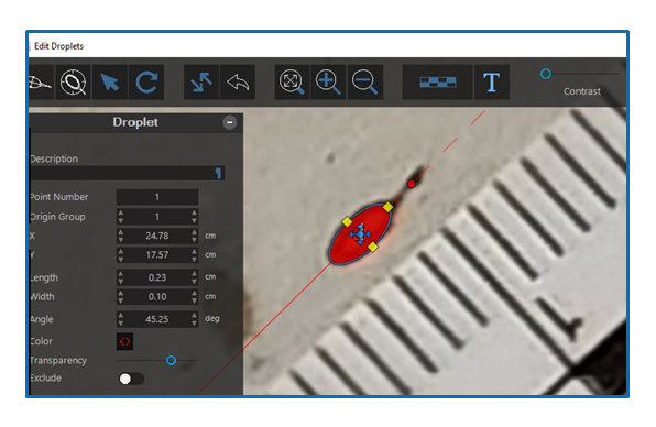
. - In the new window, zoom in on the stain or “droplet” you wish to start with and click “draw droplet” or“edge detection” to begin pulling your “virtual strings”.
- The draw droplet option allows you to manually draw the edges of the droplet/stain by clicking to select the length and width.
- The edge detection option provides you with a highlighted circle that you can use to select just the elliptical part of the droplet/stain (without the tail). The program then takes the measurement from the widest part of the droplet to its tip to auto calculate the length.
- Both options can be further adjusted by selecting “edit droplet”
 .
.
- Label the droplet to match your photos by adding to the “Description”.
- You can also change the transparency and color of your virtual strings to make adjusting your selections easier.
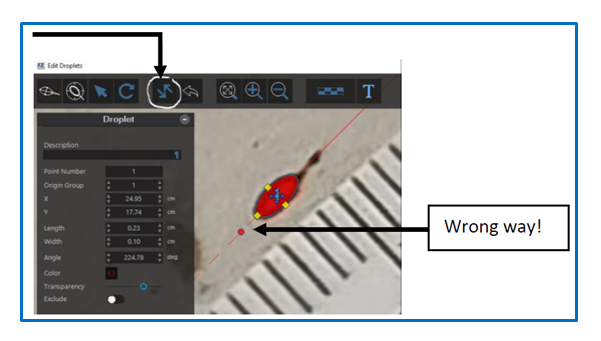
- If the tail of the droplet (dashed line) is facing the wrong way you can flip it by clicking on the “flip direction” button.
- Continue the process for multiple stains in multiple areas (don’t stick to just one pattern area!).
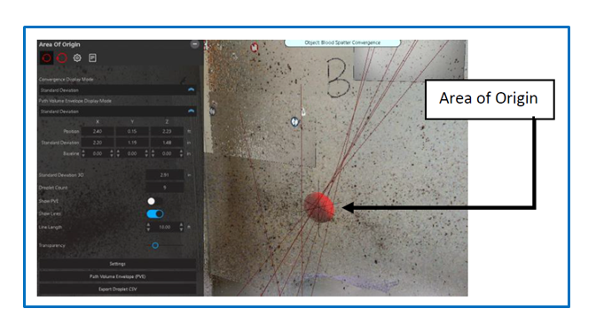
- Avoid looking at the sphere where your virtual strings intersect (also known as the area of origin) to avoid falling into confirmation bias.
- Once finished click the area of convergence to bring up your command window and to check your Standard Deviation.
- OPTIONAL – In the command window you will have several settings you can adjust as needed (such as color, transparency, line length, etc).
- NOTE – If you are working with Cast-Off stains specifically, you will want to turn on the toggle for “Show PVE”.
- When you’re ready, click the Report button
 .
. - Customize your Report to your tastes using the settings window.
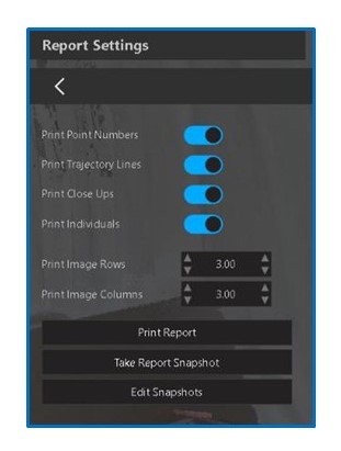
- Choose Print Report to review and add author and case information.
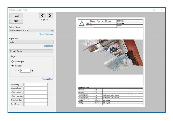
- Print.