                     
As-Built As-Built - Revit As-Built - AutoCAD VirtuSurv - VirtuSurv 2018 As-Built - Modeler VirtuSurv - VirtuSurv 2019          
BuildIT BuildIT - Projector BuildIT - Construction BuildIT - Metrology              
CAM2 CAM2 - SmartInspect CAM2 - 2023 CAM2 - 2018 CAM2 - Measure 10 CAM2 - Measure Q CAM2 - Measure X CAM2 - Measure 3/4 CAM2 - AnthroCAM CAM2 - 2019 CAM2 - 2020
CAM2 CAM2 - 2021                  
Cobalt 3D Imager 3D Imager - Cobalt                  
Cobalt Design Cobalt Design - M Cobalt Design - S Cobalt Design - Dual              
Computers Computers - All Computers                  
FARO Aras 360 & CAD Zone FARO CAD Zone - Fire & Insurance FARO CAD Zone - Crime & Crash FARO CAD Zone - CZ Point Cloud FARO CAD Zone - First Look Pro FARO 360 - Reality FARO 360 - HD FARO 360 - Blitz FARO 360 - Genius    
FARO Connect FARO Connect - Connect                  
FARO Zone present4D - present4D                  
FARO Zone 2D FARO Zone 2D - 2018 FARO Zone 2D - 2019 FARO Zone 2D - 2020 FARO Zone 2D - 2021 FARO Zone 2D - 2022 FARO Zone 2D - 2023        
FARO Zone 3D FARO Zone 3D - 2018 FARO Zone 3D - 2019 FARO Zone 3D - 2020 FARO Zone 3D - 2021 FARO Zone 3D - 2022 FARO Zone 3D - 2023 FARO Zone 3D - 2024      
FARO Zone 3D Advanced FARO Zone 3D Advanced - 2018 FARO Zone 3D Advanced - 2019 FARO Zone 3D Advanced - 2020 FARO Zone 3D Advanced - 2021 FARO Zone 3D Advanced - 2022          
FaroArm/ScanArm FaroArm/ScanArm - Quantum S FaroArm/ScanArm - Quantum M FaroArm/ScanArm - Quantum E FaroArm/ScanArm - Edge FaroArm/ScanArm - Fusion FaroArm/ScanArm - Prime FaroArm/ScanArm - Platinum FaroArm/ScanArm - Legacy Quantum FaroArm/ScanArm - Titanium FaroArm/ScanArm - Advantage
FaroArm/ScanArm FaroArm/ScanArm - Digital Template FaroArm/ScanArm - Gage FaroArm/ScanArm - Quantum S Max FaroArm/ScanArm - Quantum M Max FaroArm/ScanArm - Quantum E Max FaroArm/ScanArm - Gage Max        
GeoSLAM Software GeoSLAM Software - Connect GeoSLAM Software - Draw GeoSLAM Software - Hub GeoSLAM Software - Volumes            
GeoSLAM ZEB GeoSLAM ZEB - Horizon GeoSLAM ZEB - Horizon RT GeoSLAM ZEB - Revo GeoSLAM ZEB - Revo RT GeoSLAM ZEB - Go          
Hand Held Scanner 2D Hand Held Scanner - ScanPlan 3D Hand Held Scanner - Freestyle3D 3D Hand Held Scanner - Freestyle3D X 3D Hand Held Scanner - Freestyle3D Objects 3D Hand Held Scanner - Freestyle 2          
Language Quality HT MT AT NT INT - Internal Sales - Internal Resources Sales - Order and Quote Sales - Product Info Sales - Sales Readiness Sales - Training
Language Quality Sales - Product Launch Sales - Promotions CS - Quote to Invoice CS - Phone System CS - New Hire Training CS - General CS - Product Info CS - Licensing CS - Procedures General CS - Procedures Salesforce
Language Quality CS - Procedures Loaner CS - Procedures SAP                
Languages Language - English Language - Japanese Language - German Language - Chinese Language - Spanish Language - Italian Language - Portuguese Language - French Language - Korean  
Laser Projector RayTracer - RayTracer Laser Projector - Tracer M Laser Projector - Tracer SI              
Laser Radar Imaging Laser Radar - VectorRI                  
Laser Scanner 3D Laser Scanner - Focus S 3D Laser Scanner - Focus M 3D Laser Scanner - Focus3D 3D Laser Scanner - Focus3D X 3D Laser Scanner - Focus3D X HDR 3D Laser Scanner - Focus3D S 3D Laser Scanner - Photon 3D Laser Scanner - Focus S Plus 3D Laser Scanner - Swift 3D Laser Scanner - Focus Premium
Laser Scanner 3D Laser Scanner - Focus Core                  
Laser Tracker Laser Tracker - Vantage Laser Tracker - ION Laser Tracker - Vantage S Laser Tracker - Si Laser Tracker - X Laser Tracker - Xi Laser Tracker - Vantage E Laser Tracker - Vantage S6 Laser Tracker - Vantage E6  
Legacy Gage Legacy Gage - Bluetooth Legacy Gage - Plus Legacy Gage - Standard Legacy Gage - Power            
Legacy Software Legacy Software - CAM2 Gage Legacy Software - Gage Software Legacy Software - Insight              
Mobile Scanner Mobile Scanner - Orbis                  
PointSense PointSense - Basic PointSense - Pro PointSense - Building PointSense - Plant PointSense - Heritage PointSense - Revit CAD Plugin - TachyCAD Building CAD Plugin - TachyCAD Archeology CAD Plugin - TachyCAD Interior CAD Plugin - PhoToPlan Basic
PointSense CAD Plugin - PhoToPlan CAD Plugin - PhoToPlan Pro CAD Plugin - PhoToPlan Ultimate CAD Plugin - DisToPlan CAD Plugin - MonuMap CAD Plugin - hylasFM CAD Plugin - VirtuSurv      
RevEng RevEng - RevEng                  
ScanArm ScanArm - Design ScanArm 2.0 ScanArm - Design ScanArm ScanArm - Forensic ScanArm ScanArm - Design ScanArm 2.5C            
SCENE SCENE - Capture and Process SCENE - WebShare Server and 2Go SCENE - WebShare 2Go App SCENE - 2018 SCENE - 7.x SCENE - 6.x SCENE - 5.x SCENE - 4.x SCENE - LT SCENE - 2019
SCENE SCENE - 2go App SCENE - 2020 SCENE - 2021 SCENE - 2022 SCENE - 2023          
Serial FaroArm Serial FaroArm - Silver Serial FaroArm - Gold Serial FaroArm - Bronze              
Sphere FARO Sphere - Sphere                  
Visual Inspect Visual Inspect - App Visual Inspect - CAD Translator                
WebShare WebShare - Enterprise WebShare - WebShare Cloud                

BuildIT

Construction

FARO® Knowledge Base

Floor Flatness and Level ASTM E1155 with BuildIT Construction

BuildITConstruction-bty.png

FloorFlatnessLevel-1.pngObjective:

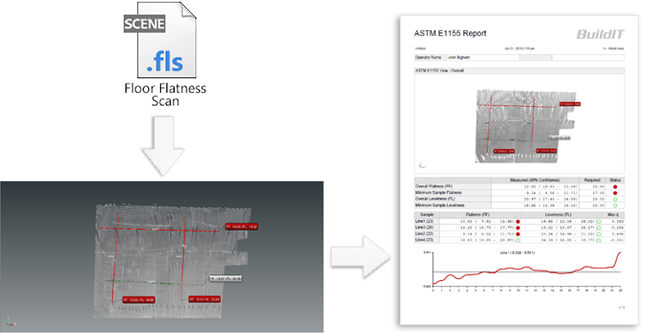
Use BuildIT Construction to Import FLS file and perform FF/FL analysis by ASTM E 1155 standard.

You’ll learn:

  • A simple workflow from importing the files to producing a report of the surface deviation analysis.
  • Opening BuildIT, import a *FLS file.
  • Split cloud
  • Creating lines representing a run.
  • Perform the FF/FL analysis.
  • Produce a Report.

Tutorial Download

If you would like to download the file used in this article, download the accompanying Training Data and extract its contents to a folder on your PC.

Training Data Download
  Download

Note: This workflow can now be completed on the Floor or Wall Analysis Workbench!

Import FLS File

  • Launch BuildIT by double-clicking the BuildIT icon on your desktop.
  • Import the WetConcrete001.fls (included in the training data) by the following method.
    • In the menu bar, click “File > Import > Import SCENE Clouds”.
    • Navigate to and select the file “WetConcrete001.fls” from the training data and click Open.
      Mod2_1_Const_2020.png
    • Once the import is completed, many times the point cloud will be outside of the current view, click the Zoom All icon ZoomAllIcon.png to view the entire project.

Zoom into the Analysis Region and Split Cloud

  • Zoom into the investigated region shown below:

    FloorFlatness-2.png
     
  • Split cloud down to the area to be analyzed.
    • Select “Refine > Split Clouds”. SplitCloudIcon.png
    • Select the imported point cloud "WetConcrete001" for “Clouds”.
    • Select the “Polygon selection” radio button and then select the polygon tool.
    • Construct a polygon line around the area shown below.
    • Ensure that “Points kept” is toggled to “Inside/above”.
    • Select Apply. ApplyIcon.png

      FloorFlatness-3.png

Create Lines for Each Run

Next we will create a line for each run, the end result will appear as shown:
FloorFlatnessLevel-4.png
TIP: Lines are created to represent runs with traditional equipment.

Hint: Use ASTM E1155 Layout Tool to streamline the run creation.

  1. Select a centerpoint for your area to test.
  2. Select the length of the runs you'd like to create (10ft minimum).
  3. Select the distance to space the lines out.
  4. Select apply.
  5. You can create as many testing positions as necessary. When the command is run, each one will have a screenshot.


  • Select “Construct > Line > Line”.
    FloorFlatnessLevel-2.png
    • Select a start point and then select an end point for the first line.
    • Click the Apply. ApplyIcon.png button in the Construct: Line Panel for each completed line.
      FloorFlatnessLevel-3.png
       
    • Repeat for several runs, as shown above.

ASTM E1155 Floor Flatness Analysis

Note: To avoid errors, save the current project before attempting the Floor Flatness Analysis.

  • Select “Evaluate > ASTM E1155 Floor Flatness Analysis”.  FFFLIcon.png
    • Select the cloud.
    • Select all the sample lines.
    • Specify the FF/FL numbers based on the project specifications. Use the defaults for this exercise.
      • Note: If the scan data is sparse, ensure you increase the contact patch diameter. Contact patch diameter represents the search distance at each sample point that the software uses to determine the measurement from the scan data.
    • Click the Apply. ApplyIcon.png button.

      FloorFlatnessLevel_2020_Fig5.png
    • Note: For the metric standard ASTM E1155M, please ensure that "Use metric standard (ASTM E1155M)" is checked.

Generate a Report from the Analysis

  • The command will automatically build a standard report.
  • Click on the Report tab and click on Generate Report. GenerateReportIcon.png
  • When prompted specify a location and name for the PDF report. The BuildIT Report Writer will now launch and create the report.

    FloorFlatnessLevel-6.png

Recap:

Congratulations, you have completed the ASTM E1155 module! By now you should have a grasp of the following:

  • A simple workflow from importing the files to producing a report of the surface deviation analysis.
  • Opening BuildIT, import a *FLS file.
  • Split cloud
  • Creating lines representing a run.
  • Preform the FF/FL analysis.
  • Produce a Report.