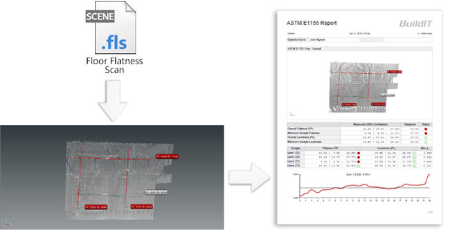
Floor Flatness and Level ASTM E1155 with BuildIT Construction
 Objective:
Use BuildIT Construction to Import FLS file and perform FF/FL analysis by ASTM E 1155 standard.
You’ll learn:
- A simple workflow from importing the files to producing a report of the surface deviation analysis.
- Opening BuildIT, import a *FLS file.
- Split cloud
- Creating lines representing a run.
- Perform the FF/FL analysis.
- Produce a Report.
Tutorial Download
If you would like to download the file used in this article, download the accompanying Training Data and extract its contents to a folder on your PC.
Note: This workflow can now be completed on the Floor or Wall Analysis Workbench!
Import FLS File
- Launch BuildIT by double-clicking the BuildIT icon on your desktop.
- Import the WetConcrete001.fls (included in the training data) by the following method.
- In the menu bar, click “File > Import > Import SCENE Clouds”.
- Navigate to and select the file “WetConcrete001.fls” from the training data and click Open.

- Once the import is completed, many times the point cloud will be outside of the current view, click the Zoom All icon
 to view the entire project.
Zoom into the Analysis Region and Split Cloud
- Zoom into the investigated region shown below:

- Split cloud down to the area to be analyzed.
- Select “Refine > Split Clouds”.

- Select the imported point cloud "WetConcrete001" for “Clouds”.
- Select the “Polygon selection” radio button and then select the polygon tool.
- Construct a polygon line around the area shown below.
- Ensure that “Points kept” is toggled to “Inside/above”.
- Select Apply.


- Select “Refine > Split Clouds”.
Create Lines for Each Run
Next we will create a line for each run, the end result will appear as shown:

TIP: Lines are created to represent runs with traditional equipment.
Hint: Use ASTM E1155 Layout Tool to streamline the run creation.
- Select a centerpoint for your area to test.
- Select the length of the runs you'd like to create (10ft minimum).
- Select the distance to space the lines out.
- Select apply.
- You can create as many testing positions as necessary. When the command is run, each one will have a screenshot.
- Select “Construct > Line > Line”.

- Select a start point and then select an end point for the first line.
- Click the Apply.
 button in the Construct: Line Panel for each completed line.

- Repeat for several runs, as shown above.
ASTM E1155 Floor Flatness Analysis
Note: To avoid errors, save the current project before attempting the Floor Flatness Analysis.
- Select “Evaluate > ASTM E1155 Floor Flatness Analysis”.

- Select the cloud.
- Select all the sample lines.
- Specify the FF/FL numbers based on the project specifications. Use the defaults for this exercise.
- Note: If the scan data is sparse, ensure you increase the contact patch diameter. Contact patch diameter represents the search distance at each sample point that the software uses to determine the measurement from the scan data.
- Click the Apply.
 button.

- Note: For the metric standard ASTM E1155M, please ensure that "Use metric standard (ASTM E1155M)" is checked.
Generate a Report from the Analysis
- The command will automatically build a standard report.
- Click on the Report tab and click on Generate Report.

- When prompted specify a location and name for the PDF report. The BuildIT Report Writer will now launch and create the report.

Recap:
Congratulations, you have completed the ASTM E1155 module! By now you should have a grasp of the following:
- A simple workflow from importing the files to producing a report of the surface deviation analysis.
- Opening BuildIT, import a *FLS file.
- Split cloud
- Creating lines representing a run.
- Preform the FF/FL analysis.
- Produce a Report.

