Concrete Society (CS) TR34 Workflow with BuildIT Construction
Objective:
In this tutorial, you will learn how to perform the Concrete Society TR34 test for properties E and F. This test consists of two grid based sampling methods with tolerances defined in Table 3.1 of the standard, which define various floor types.
You’ll Learn:
• How to define sample lines
• How to run the CS TR34 Analysis in BuildIT Construction
• How to create a report from the analysis
Tutorial Download
If you would like to download the file used in this article, download the accompanying Training Data and extract its contents to a folder on your PC.
Define Sample Lines
- The TR34 analysis in BuildIT Construction requires two lines which represent the area to analyze.
- These lines should:
- Be perpendicular
- Encompass the area to analyze
- A good example is shown below. The area that will be analyzed will be the area in red. Areas without points or sparse points will be ignored.

- These lines should:
- To define the sample lines, use the Construct: Line command
 . Remember, the lines direction is set from the start to end point selected. For this exercise, create two lines as shown.


- If there are multiple test areas, simply change the name of the lines to represent a different area.
- For example, naming the sections as “section1-1” and “section2-2” will run the analysis on the two areas.

- For example, naming the sections as “section1-1” and “section2-2” will run the analysis on the two areas.
- If the lines are drawn in the wrong direction and the analysis run on the wrong area, you can simply Undo before the analysis. You can display the lines direction by selecting the lines and changing the Show direction vector in the Curve manager.

- You can also reverse the direction of the line if necessary by using Edit: Curves: Reverse

Run the CS TR34 Analysis
- Start the analysis command by selecting the CS TR34 Analysis command.

- Select the point cloud and the created lines created to analyze.

- For Floor class, select FM4 for this example.
- The floor class comes from the Table 3.1 of the CS TR34 standard. Selecting the floor class sets the tolerances for the two properties E and F. Property E controls the levelness of the area and property F controls the flatness. Both values are reported by area and with a 95% confidence interval, as required by the standard, in the report.

- The floor class comes from the Table 3.1 of the CS TR34 standard. Selecting the floor class sets the tolerances for the two properties E and F. Property E controls the levelness of the area and property F controls the flatness. Both values are reported by area and with a 95% confidence interval, as required by the standard, in the report.
- Set the Contact patch diameter to 3 inches, (or around 76mm).
- Contact patch diameter represents the search distance at each sample point that the software uses to determine the measurement from the scan data.
- Select Apply to run the command.


Note: Annotations can be edited in the manager as shown. This is a combination of editing the background and the font size in settings.
Create a Report
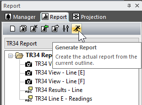
• To create a report, simply select the Run Report command in the Report manager.


Recap
Congratulations, you have completed the module! By now you should have a grasp of how to:
- Define sample lines for the analysis.
- Run the CS TR34 analysis.
- Create a report of the analysis results.

