                     
As-Built As-Built - Revit As-Built - AutoCAD VirtuSurv - VirtuSurv 2018 As-Built - Modeler VirtuSurv - VirtuSurv 2019          
BuildIT BuildIT - Projector BuildIT - Construction BuildIT - Metrology              
CAM2 CAM2 - SmartInspect CAM2 - 2023 CAM2 - 2018 CAM2 - Measure 10 CAM2 - Measure Q CAM2 - Measure X CAM2 - Measure 3/4 CAM2 - AnthroCAM CAM2 - 2019 CAM2 - 2020
CAM2 CAM2 - 2021                  
Cobalt 3D Imager 3D Imager - Cobalt                  
Cobalt Design Cobalt Design - M Cobalt Design - S Cobalt Design - Dual              
Computers Computers - All Computers                  
FARO Aras 360 & CAD Zone FARO CAD Zone - Fire & Insurance FARO CAD Zone - Crime & Crash FARO CAD Zone - CZ Point Cloud FARO CAD Zone - First Look Pro FARO 360 - Reality FARO 360 - HD FARO 360 - Blitz FARO 360 - Genius    
FARO Connect FARO Connect - Connect                  
FARO Zone present4D - present4D                  
FARO Zone 2D FARO Zone 2D - 2018 FARO Zone 2D - 2019 FARO Zone 2D - 2020 FARO Zone 2D - 2021 FARO Zone 2D - 2022 FARO Zone 2D - 2023        
FARO Zone 3D FARO Zone 3D - 2018 FARO Zone 3D - 2019 FARO Zone 3D - 2020 FARO Zone 3D - 2021 FARO Zone 3D - 2022 FARO Zone 3D - 2023 FARO Zone 3D - 2024      
FARO Zone 3D Advanced FARO Zone 3D Advanced - 2018 FARO Zone 3D Advanced - 2019 FARO Zone 3D Advanced - 2020 FARO Zone 3D Advanced - 2021 FARO Zone 3D Advanced - 2022          
FaroArm/ScanArm FaroArm/ScanArm - Quantum S FaroArm/ScanArm - Quantum M FaroArm/ScanArm - Quantum E FaroArm/ScanArm - Edge FaroArm/ScanArm - Fusion FaroArm/ScanArm - Prime FaroArm/ScanArm - Platinum FaroArm/ScanArm - Legacy Quantum FaroArm/ScanArm - Titanium FaroArm/ScanArm - Advantage
FaroArm/ScanArm FaroArm/ScanArm - Digital Template FaroArm/ScanArm - Gage FaroArm/ScanArm - Quantum S Max FaroArm/ScanArm - Quantum M Max FaroArm/ScanArm - Quantum E Max FaroArm/ScanArm - Gage Max        
GeoSLAM Software GeoSLAM Software - Connect GeoSLAM Software - Draw GeoSLAM Software - Hub GeoSLAM Software - Volumes            
GeoSLAM ZEB GeoSLAM ZEB - Horizon GeoSLAM ZEB - Horizon RT GeoSLAM ZEB - Revo GeoSLAM ZEB - Revo RT GeoSLAM ZEB - Go          
Hand Held Scanner 2D Hand Held Scanner - ScanPlan 3D Hand Held Scanner - Freestyle3D 3D Hand Held Scanner - Freestyle3D X 3D Hand Held Scanner - Freestyle3D Objects 3D Hand Held Scanner - Freestyle 2          
Language Quality HT MT AT NT INT - Internal Sales - Internal Resources Sales - Order and Quote Sales - Product Info Sales - Sales Readiness Sales - Training
Language Quality Sales - Product Launch Sales - Promotions CS - Quote to Invoice CS - Phone System CS - New Hire Training CS - General CS - Product Info CS - Licensing CS - Procedures General CS - Procedures Salesforce
Language Quality CS - Procedures Loaner CS - Procedures SAP                
Languages Language - English Language - Japanese Language - German Language - Chinese Language - Spanish Language - Italian Language - Portuguese Language - French Language - Korean  
Laser Projector RayTracer - RayTracer Laser Projector - Tracer M Laser Projector - Tracer SI              
Laser Radar Imaging Laser Radar - VectorRI                  
Laser Scanner 3D Laser Scanner - Focus S 3D Laser Scanner - Focus M 3D Laser Scanner - Focus3D 3D Laser Scanner - Focus3D X 3D Laser Scanner - Focus3D X HDR 3D Laser Scanner - Focus3D S 3D Laser Scanner - Photon 3D Laser Scanner - Focus S Plus 3D Laser Scanner - Swift 3D Laser Scanner - Focus Premium
Laser Scanner 3D Laser Scanner - Focus Core                  
Laser Tracker Laser Tracker - Vantage Laser Tracker - ION Laser Tracker - Vantage S Laser Tracker - Si Laser Tracker - X Laser Tracker - Xi Laser Tracker - Vantage E Laser Tracker - Vantage S6 Laser Tracker - Vantage E6  
Legacy Gage Legacy Gage - Bluetooth Legacy Gage - Plus Legacy Gage - Standard Legacy Gage - Power            
Legacy Software Legacy Software - CAM2 Gage Legacy Software - Gage Software Legacy Software - Insight              
Mobile Scanner Mobile Scanner - Orbis                  
PointSense PointSense - Basic PointSense - Pro PointSense - Building PointSense - Plant PointSense - Heritage PointSense - Revit CAD Plugin - TachyCAD Building CAD Plugin - TachyCAD Archeology CAD Plugin - TachyCAD Interior CAD Plugin - PhoToPlan Basic
PointSense CAD Plugin - PhoToPlan CAD Plugin - PhoToPlan Pro CAD Plugin - PhoToPlan Ultimate CAD Plugin - DisToPlan CAD Plugin - MonuMap CAD Plugin - hylasFM CAD Plugin - VirtuSurv      
RevEng RevEng - RevEng                  
ScanArm ScanArm - Design ScanArm 2.0 ScanArm - Design ScanArm ScanArm - Forensic ScanArm ScanArm - Design ScanArm 2.5C            
SCENE SCENE - Capture and Process SCENE - WebShare Server and 2Go SCENE - WebShare 2Go App SCENE - 2018 SCENE - 7.x SCENE - 6.x SCENE - 5.x SCENE - 4.x SCENE - LT SCENE - 2019
SCENE SCENE - 2go App SCENE - 2020 SCENE - 2021 SCENE - 2022 SCENE - 2023          
Serial FaroArm Serial FaroArm - Silver Serial FaroArm - Gold Serial FaroArm - Bronze              
Sphere FARO Sphere - Sphere                  
Visual Inspect Visual Inspect - App Visual Inspect - CAD Translator                
WebShare WebShare - Enterprise WebShare - WebShare Cloud                
FARO® Knowledge Base

Deviation Grid with BuildIT Construction

Objective

Use the Create Grid Deviation to generate a deviation map and output a labeled grid of points to dxf for a selected area.

You’ll Learn

  • Importing scan data.
  • Creating reference surfaces.
  • Performing the Deviation Grid command.

Tutorial Data

Data Link: Downloads

Import scan data

  1. Go to FileBuildit_Import CPE CLouds.png
  2. Import 
  3. Import CPE Clouds to import the example scan.
    Note: CPE files can be exported from FARO SCENE or WebShare. Other scan data types can also be used for this workflow.

    Buildit_Import CPE CLouds Device.png

Create reference surface

To create a reference surface:

  • Restore a top view of the point cloud by selecting the top view on the toolbar or select "Alt + 8" on a keyboard.
    Buildit_Top surface.png
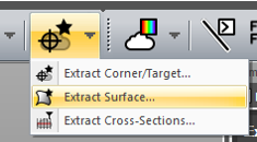
  • Go to Refine > Extract Surface to extract a best fit and level plane
    • Ensure that the surface type is selected as “Plane” and use the rectangular selection to select the area of the floor to analyze.
    • Once the rectangular selector is enabled for the “Points” section, you can either double left click on the screen to start the selection or use CTRL + Left Click to start the selection.
      Buildit_extract surface.png
      Buildit_extract surface plane 1.png
      Buildit_plane surface.png
      Buildit_Constrain normalaxis.png
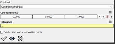
      • For "Constraint" > Select "Constrain normal/axis" to make the plane perfectly level.
      • For “Constaint normal” > Select Z
      • For "Tolerance" > select 1” or 25 mm. Note: Version 2020.5 and after, you can also enter “1 in” or “25 mm” to automatically convert to current units. This also accepts imperial unit imports such as “1 ft 1 1/2 in” and will convert them to decimals.
  • Select Apply.
    Buildit_tolerance.png
    Buildit_extract surface plane view.png

Perform the Deviation Grid command

  • Start the "Create Deviation Grid Command"
  • Select the imported point cloud for “Cloud” and the plane extracted for the “Plane”.
Buildit_create deviation grid.png

Grid settings: 

  • Origin - Select a point in the lower left.
    • This is where the grid will start.
  • Horizontal Bound - Select a point in the lower right.
    • This defines the length of the search area.
  • Vertical Bound - Select a point in the upper left.
    • This defines the height of the search area.
  • Grid Size - Enter 120 inch.
    • This defines how often to sample the point cloud in a grid pattern. Lower values will produce more annotations.
  • Tolerance - Enter 0.25 inch.
    • Areas above or below this value will be highlighted.
      Buildit_origin bound.png

The Deviation Settings:

  • Create Surface Deviation - Enable this option.
    • This will colorize the point cloud based on deviation from the created reference plane.
  • Deviation Type
    • Absolute (Pass/Fail) - Select this option.
      • This will colorize points above our set tolerance as red and below as purple.
    • Relative (Rainbow)
      • Relative will create a rainbow of colors, representing deviation from the reference surface.

DXF Export

  • Export Points to DXF - Enable this option.
    • The annotations create will be exported as points and text labels to DXF automatically when running the command.
  • DXF Export Type - Select Deviation.
    • Deviation
      • This will report the average deviation near the grid sample location in the DXF.
    • Absolute
      • This will report the actual value of the selected deviation axis. You can use this to label elevations at each grid point for instance.
  • DXF Label Deviation Axis - Select Z.
    • This allows for the command to be used for floors as well as elevator shafts. Ensure that you select the proper axis where the deviation should be, as this is what is exported to the DXF file.
      Buildit_Deviation settings.png
  • Run the analysis.
    Buildit_decimal display.png

Note: You can adjust the decimals shown in BuildIT under File > Settings > Display > Default Units > Distance Decimals.

Recap

  • Congratulations, you have completed the module and learned how to:
    • Import scan data.
    • Create a reference plane.
    • Perform the Grid Deviation command.