Measuring Helical Pitch of a Spline Gear
Overview
Most dimensional measurement systems approach measuring an angle as a ‘two dimensional’ endeavor. Therefore, obtaining a helical pitch of a spline gear may pose a challenge for companies looking to inspect or reverse engineer a spline gear. This document describes a process that will allow a user of a portable cmm, such as a FaroArm® or Laser Tracker, to accurately measure the helical pitch of a spline gear.
Required
- FaroArm or Laser Tracker
- CAM2 Software
- CAD package capable of flattening curved surfaces into 2 dimension / planar surfaces
- CAD software must have unroll type function
Quick Steps
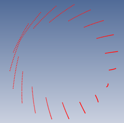
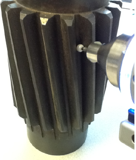
- While nestling a hard probe between the teeth of the spline gear (pictured below right), collect a series of evenly spaced points. Repeat this between each set of teeth. The result will resemble the below left picture.
Note: The probe must be large enough to nestle between the teeth.
- Construct a cylinder by fitting it through the previously measured points.
- Export the points and clinder from CAM2 using the IGES format option.
- Import the IGES file into the CAD package. You should see something on your screen similar to the picture below.
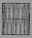
- Unroll the cylinder and at least one group of points from to convert them from 3 Dimesional features to 2 Dimesional. The steps to do this in each CAD package will be different.
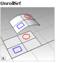
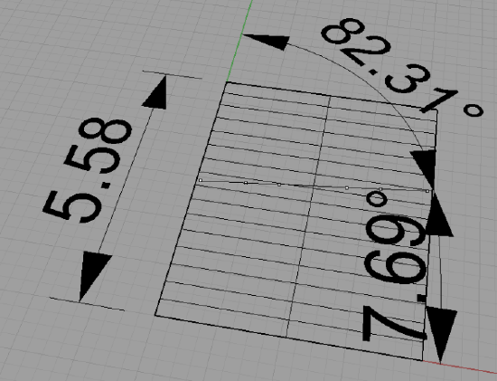
- The unrolled points that represented a helical spline in 3D will create a straight line in two dimensions. Construct a line through the unrolled points and simply create a dimension from either or both baselines of the unrolled cylinder to the line. This is the helical pitch.