Scanning Complex Part Surfaces With the Laser Line Probe (LLP) or ScanArm
Overview
You get consistent high quality results, and are the most efficient, when you use best practices for scanning complex part surfaces with the Laser Line Probe (LLP) or FARO ScanArm. Before you begin your project, review the video and the list below for tried-and-true pointers that yield foolproof non-contact scanning.
Video
In this video, watch how best practices are applied. Paying attention to how he handles the LLP, and how he places his body to get the most accurate results.
Best Practices
- Angle the LLP correctly depending on the type of surface you are scanning.
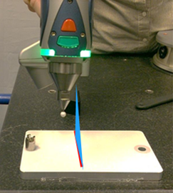
- For non-reflective or matte surfaces, the angle of the laser beam should be perpendicular to the part surface. This enables the camera to get the most return from the laser.

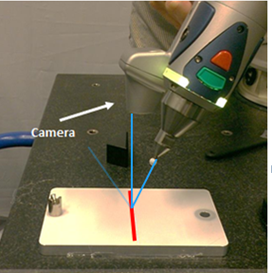
- For reflective surfaces, the angle of laser beam should be at an angle to the part surface. Achieve the optimal angle by aligning the camera perpendicular to the part surface. This ensures that noise reflections are projected away from the camera.

- For non-reflective or matte surfaces, the angle of the laser beam should be perpendicular to the part surface. This enables the camera to get the most return from the laser.
- When calibrating the V3 or ES LLP, start with the Normal algorithm, then adjust the Advanced settings to match the surface finish.
- The Normal setting is good for matte surfaces that are not too dark. The exposure adjusts automatically withing a range of 0-50.
- Full is good for darker matte surfaces. The exposure adjusts automatically within a range from 0 to maximum.
- Highly Reflective is good for reflective surfaces. The exposure adjusts automatically within a range from 0 to maximum, and also adjusts other settings to better manage gloss.
- When calibrating the HD LLP, start with the Automatic-Normal algorithm, then adjust the settings and filters to match the surface finish.
- The Reflection Filter removes data noise created by shinny surfaces.
- The Automatic-HDR algorithm normalizes areas with high contrasts between dark and light areas
- Scan in Fixed Exposure if room lighting conditions significantly affect the quality of your scan. Scanning with Fixed Exposure instead of “Normal” will guarantee consistency in data quality if external lighting disrupts the camera sensor. User can start at 400 ms and adjust the exposure based on the how light/dark the part surface is.
-
Hold the LLP at a consistent distance from part surfaces while you are moving the LLP over the part to reduce noise. The LLP has a tighter point density in the near field, when you hold the LLP close, than it does in the far field, when you hold the LLP further away. Increased noise in the far field is related to the distance the laser beam travels to the surface and back to the camera. When the laser beam travels further, the return signal is not as defined as when it is up close. It is similar to the beam of a flashlight. When you shine the beam up close, the light seems brighter and the edges of the beam are more defined. When you shine the beam further away, the light seems less bright and the the edges of the beam are more defused.
- Set the Accuracy Mode to High in the Settings dialog box. This setting filters out points further from the scanner in the far field. While this reduces the depth of field from approximately 4.5 inches (115 mm) to 1.25 inches (32 mm), tests on calibrated surfaces with a matte finish show the scan noise is reduced by approximately 50%. Setting to High Accuracy mode for V1, V2, V3, and ES may increase the accuracy, but for the HD model, it will only decrease the noise significantly.
- Hold the grip handle steady while you are moving the LLP over part surfaces. Avoid rotating it.
- Position part surfaces closer to the LLP rather than further from it.
- Scan one adjoining surface then the other when scanning surfaces that meet at a corner. First position the LLP perpendicular to one surface, scan it completely, and stop. Then, reposition the LLP perpendicular to the adjoining surface, scan it completely, and stop. Do not move the LLP as if you are rolling over the corner of the two adjoining surfaces.
- Do not overreach when scanning. Position your own body, arms and hands, such that the section of the part you are scanning fits comfortably within your reach and body stance.
- Divide your scanning project into logical parts that enable you to observe best practices when scanning.
See Also
- Calibration Settings for Optimal Quality From the Laser Line Probe (LLP)
- Recommended Anti-Reflective Powder Spray for Use with the Laser Line Probe
Keywords:
scan corners, scan complex parts, scan difficult parts, holding the LLP, pointing the LLP, normal position for the LLP

