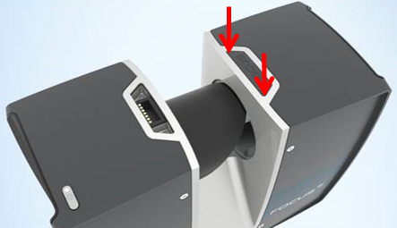
3D CAD Model for the Accessory Interface Ports on the Focus Laser Scanner
Quick Steps
Click this link to download a 3D model in .STEP file format. This file contains all the dimensions you need to construct your own accessory interface port connector. Most CAD applications, such as AutoCAD or SolidWorks, can open a .STEP file.
| Date | |
|---|---|
| Mar 2018 |
Overview
The FARO® FocusS series laser scanners are designed with automation in mind. To anticipate and support how you might want to automate the scanner's functionality, two accessory interface ports are provided on top of the scanner. Pressing down on the port cover corners with the acute-angles leverages the cover up so you can lift it off to reveal the port beneath. If pressing on one corner does not work, try the other.
These ports make it possible to supply power to the scanner, add data to the scan data stream, and to power external devices using the scanner’s power supply. Refer to the Automation Interfaces manual for the signal and power specifications.

The See Also section in this article provides more information about building custom applications to control the scanner or extend its functionality.
See Also
- SDK File Download for SCENE
- Automation Interface Manual for the Focus S
- User Manual for the Focus M70 and S70/S150/S350
Keywords
aux ports, auxiliary ports, custom solutions, electrical interface, electrical bus, power supply, running external devices with the Focus S, external accessory

