Wired Ethernet Settings and Window's Configuration for the Laser Tracker
Overview
This article will cover:
- Ethernet configurations for Windows (Windows 10, Windows 7, and Windows XP) & setup for PC with the Laser Tracker and Tracker Utility
- Ethernet Cable Requirements
- Connection Problems
Ethernet Cable Requirements
The FARO® Laser Tracker connects to a computer using a 100 Mbps connection using a CAT 5 Ethernet cable.
The maximum recommend cable run length for CAT 5 Ethernet cables, as specified by the Electronic Industries Association and Telecommunications Industry Association (EIA/TIA), is 100 meters or 328 feet.
Ethernet Configurations
Windows 10
Quick Steps
-
Download and Install the Latest Tracker Utility
-
Check the Network Settings of the PC
-
Activate the Laser Tracker and Connect Using the Tracker Utility
-
Connection Method to CAM 2 Measure 10 (optional)
Prepare
|
Time to Complete |
15 minutes |
|
Skills Needed |
|
|
Prerequisites |
|
|
Compatibility |
|
|
Supported Software |
|
Download and Install the Latest Tracker Utility
- Click here to download the latest FARO® Laser Tracker Utilities.
- Extract the contents of the downloaded file to the desktop of the computer you use with the Laser Tracker.
- Temporarily disable any anti-virus software, then right click the setup.exe file and select "Run as administrator"
Check the Network Settings of the PC
- Temporarily disable the Windows firewall.
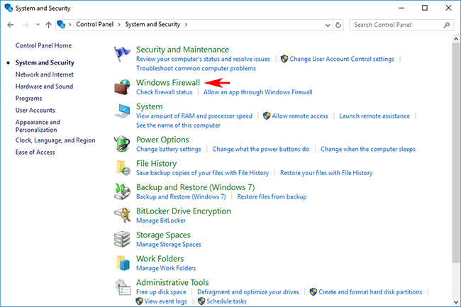
- Right-click on the Windows Start icon and then left-click on Control Panel. Once the Control Panel opens, click on System and Security.
![]()
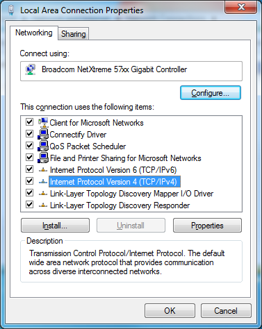
- On the next screen, click Windows Firewall.
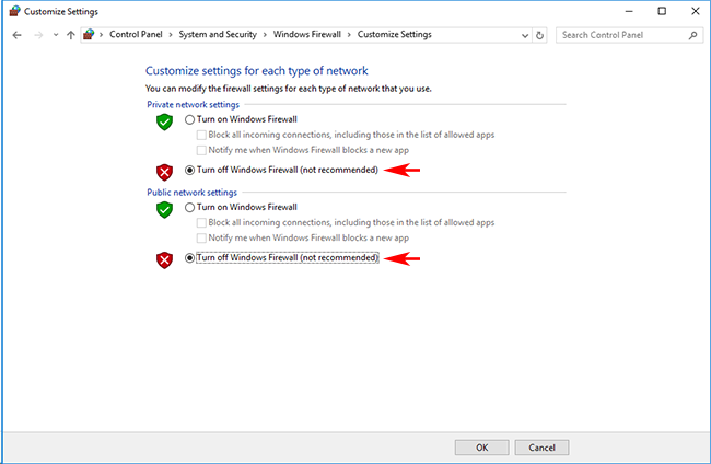
- Set both Private and Public networks to Off, then click OK.
- Configuring Network Settings
- Right-click on the Windows Start icon and then left-click on Network Connections. Next right-click on Local Area Connection and then left-click on Properties.
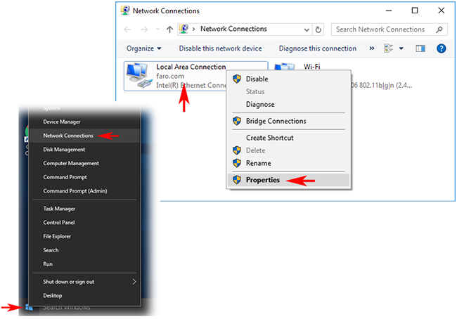
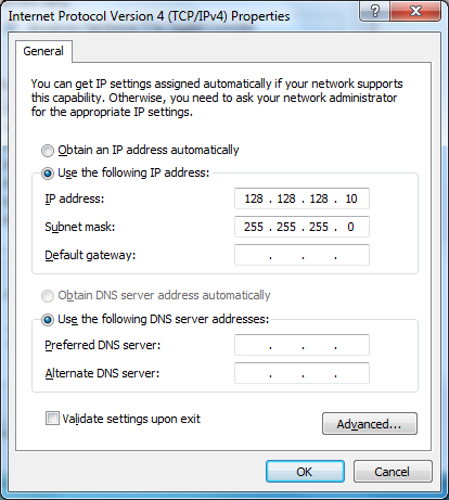
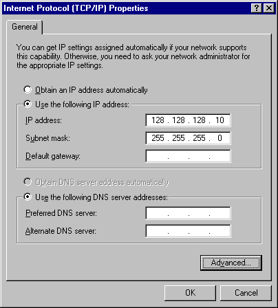
- Click on Internet Protocol Version 4 (TCP/IPv4) and then click the Properties button.
![]()
- Select the "Use the following IP address" radio button, enter the fixed IP address (128.128.128.10), the subnet mask (255.255.255.0), and then click OK.
![]()
- Normally, the Tracker's factory-set IP address is 128.128.128.100.
- Be sure that the IP address of the computer is not the same as the Laser Tracker.
- Disable user account control
- From "User Account" of the control panel, click "Change User Account Control Settings". If it can not be found, enter "UAC" in the search field and click "Change User Account Control Settings" displayed on the search list to open it.
![]()
- Lower the slide bar as shown below and set it to "Do not notify".
![]()
Activate the Laser Tracker and Connect Using the Tracker Utility
-
Turn on the Laser Tracker. For Vantage models, check the connection mode at startup. After turning on the power, check the status of the light on the Master Control Unit (MCU).
- Wired connection: After turning on the power, only light ① is on.
- Wireless connection: After turning on the power, lights ① and ② blink simultaneously.
![]()
- If the Tracker is configured for a wired connection, proceed to the next step. If the Tracker is configured wireless connection it must be reconfigured for a wired connection, See the User Manual for instructions.
- Starting the Tracker Utility
- Make sure the Ethernet cable is connected and start Tracker Utility. A crossover Ethernet cable is required for Vantage and ION models, for VantageS and E models use the proprietary cable provided.
![]()
- For Vantage models: In the "Serial Number or IP Address" field, enter the last four digits of the serial number as listed on the Laser Tracker head.
- For ION and X models: Enter the IP address of the equipment in the "Serial Number or IP Address" column. The factory-set IP address is set to (128.128.128.100).
- After completing the entry, click "Connect".
- If you can not connect, check the IP address of the equipment.
- Click the Find Trackers button. When the Find Trackers window opens, uncheck "Match the IP Address ..." and click the "Find Trackers" button.
![]()
- Check the available Tracker(s) that appear on the list. Verify that the IP address setting is correct and that Wi-Fi is set to OFF.
![]()
- If the Laser Tracker is not displayed on the list, confirm "Check the Network Settings of the PC" again, or try restarting PC and Laser Tracker.
- If you are satisfied with the results, close the "Find Tackers" window and click "Connect".
- Verify the Tracker Utility has established a connection.
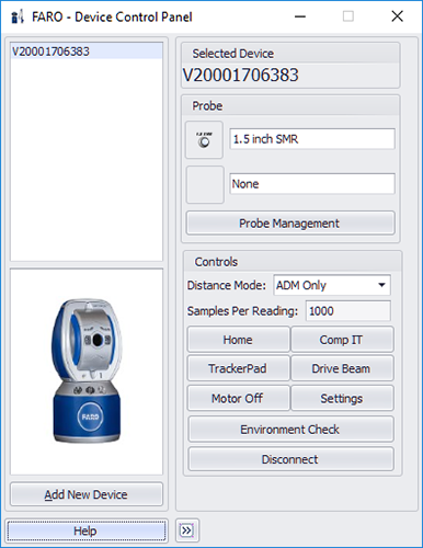
- When Tracker Utility is connected the menu will be displayed. To terminate the connection, click the "Disconnect" button.
![]()
Connection Method to CAM2 Measure (optional)
- Open CAM2 Measure and display the "Measuring instrument control panel". You can access it from the keyboard shortcut "P". If the Laser Tracker is displayed on the equipment list, the connection is successful.
- VantageS requires CAM2 Measure 10.6.7 or later.
- Vantage requires CAM2 Measure 10.1 or later.
- If there is no display on the equipment list, click the "Add instrument" button and add the equipment.
- For Vantage models: Select "Tracker ID" and enter the last four digits of the serial number as entered on the tracker head then click the Connect button.
- For ION and X models: Select "IP address" and enter the IP address of the Tracker then click the Connect button. The factory-set IP address is set to (128.128.128.100).
![]()
Windows 7
The network cards on a Windows 7 computer can be configured to communicate with the FARO® Laser Tracker by the following instructions. If desired, you can download the instructions here as a Word document:
| Laser Tracker - Windows 7 |
Quick Steps
- On the desktop, click the Start menu, and search for “View Network Connections” and select it.
- Alternatively, you can go to Control Panel > Network and Internet > Network and Sharing Center and choose “Change adapter settings” from the list on the left hand side.
- There should be at least one "Local Area Connection" icon. Use your mouse pointer to highlight each icon. The Tool Tip Should state the make and model of the Network Adapter.
Note: If there is more than one "Local Area Connection" you will need to determine which one is the one being used for the FARO Laser Tracker system. Modern computers have a built-in network connection. Some computers may have had another Ethernet board or Network Adapter installed.
- Right-click on the "Local Area Connection" icon linked with the Laser Tracker and select Properties.
- Ensure that "Internet Protocol 4 (TCP/IPv4)" has a check mark. Select it and click the Properties button.
- Select the "Use the following UP address" radio button and add the following:
IP address: 128.128.128.X (where X is any number between 0 and 99)
Subnet mask: 255.255.255.0
- Click OK to return to the "Local Area connection Properties" window.
- Press Close to save changes. You will be returned to the Network Connections screen.
- Right-click on the "Local Area Connection" icon that is being used for the Tracker and select Properties a second time.
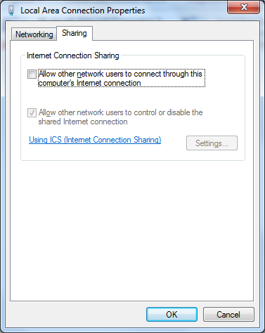
- Select the Sharing tab at the top of the Properties window.
- Ensure that "Allow other network users to connect through this computer's Internet connection" is not selected. If it is, remove the check mark.
- Click OK. You will be returned to the Network Connection screen. Close the screen by selecting the "X" in the right-hand corner.
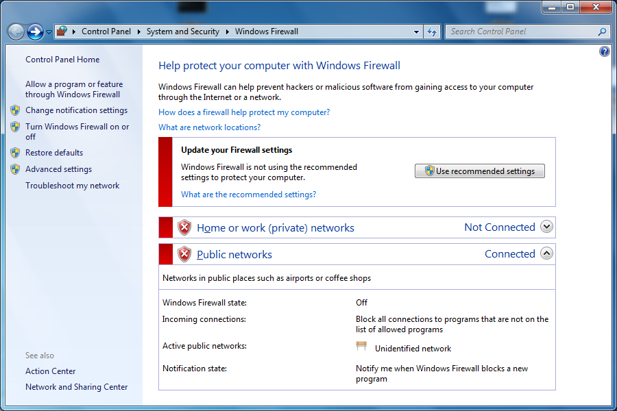
- On the desktop, click the Start Menu and search for "Windows Firewall" and select it. (Do not choose Windows Firewall with Advanced Settings).
Alternatively, you can go to Control Panel > System and Security > Windows Firewall.
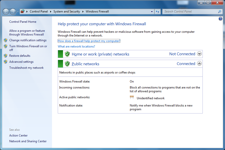
- Select "Turn Windows Firewall on or off" from the left-hand side.
- Select "Turn off Windows Firewall (not recommended)" for both Private and Public network location settings.
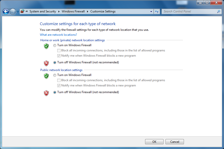
- Click OK.
Note: A notification recommending that you Update you Firewall setting will be displayed. Do not press “Use recommended settings” or communication problems with the tracker will occur. If the computer is also connected to your corporate network using a second network adaptor or using wireless, there is still protection from the hardware firewall monitoring communications between the computer and the internet.
- Close this screen by selecting the "X" in the right-hand corner to return to the desktop.
- Ensure the Ethernet cable is connected to computer and MCU. The connection on the MCU is next to On/Off switch.
- To verify that communication is present, from the Windows Desktop, click on the Start menu, and do a search for "cmd" and select it. A DOS prompt will open.
- Type 'ping 128.128.128.100' and press Enter.
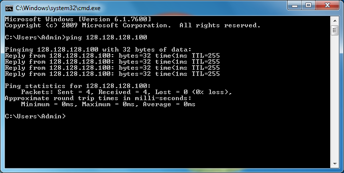
- If you receive a "reply", then the computer and Tracker are able to communicate with each other. If you received a "Request timed out", then the computer and tracker are not able to communicate with each other. Possible causes are: The tracker is not connected to the computer or the Ethernet cable is not working properly.
The tracker is not turned on.
‘Local Area Connection’ (or the network adaptor that was just configured) is Disabled.
To Enable it, go back to “View Network Connections”, select it, right click and choose Enable
‘Local Area Connection’ is not the network adaptor that the tracker is connected to (this applies if there are multiple network connections on the computer)
Someone has changed the tracker's IP address from its default of 128.128.128.100 and a ‘Local Area Connection’ needs to be assigned a different IP address than the one described in Step 6. This IP address would need to be compatible with tracker's new IP address that it was manually configured with. - Close the DOGS prompt by selecting the 'X' in the upper-right corner to return to the desktop.
If problems connecting to the tracker persist, the inspection software (such as CAM2) may not be configured to communicate with the tracker correctly or there may be 3rd party firewall software installed on the computer that needs to be disabled.
-----
Windows XP
Overview
The network cards on a Windows XP computer can be configured to communicate with the FARO® Laser Tracker by the following instructions. If desired, you can download the instructions here as a Word document:
| Laser Tracker - Windows XP |
Quick Steps
-
On the desktop, right-click on the ‘My Network Places’ and select ‘Properties’.
- There should be at least one ‘Local Area Connection’ icon. Highlight each icon with your mouse and The Tool Tip should state the make and model of the Network Adapter.

Note: If there is more than one ‘Local Area Connection’ you will need to determine which one is the one being used for the Laser Tracker. For most laptops there will be a built-in network connection. An Ethernet board may need to be added for some older desktop computers.
- Disable all network connections that are not in use.
- Right-click on the ‘Local Area Connection’ icon that is being used for the tracker and select ‘Properties’.
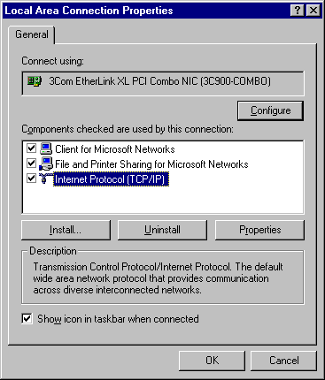
- Ensure that there is no firewall installed. If there is a firewall, disable it.
- Ensure the ‘Internet Protocol (TCP/IP) is checked and selected. Next, click on the ‘Properties’ button.
- Select the ‘Use the following IP address’ radio button and add the following:
IP address: 128.128.128.X (where X is any number between 0 and 99)
Subnet mask: 255.255.255.0
- Click OK to return to the ‘Local Area Connection Properties’ window.
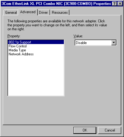
- Click ‘Configure’ and then select the ‘Advanced’ tab. Check under Property for a listing named ‘Cable Type’. If there is a ‘Cable Type’ listed, select it then ensure the Value is set to ‘Auto’ or ‘Auto Detect’.
Next click the OK button. If ‘Cable Type’ is not listed simply click the cancel button.
- When finished, click ‘OK’ to exit Network Properties, and click ‘Yes’ to reboot if prompted.
- Ensure the Ethernet cable is connected to computer and the MCU. The connection on the MCU is next to the On/Off switch.
- As a check click on the ‘Start’ button on the Windows Desktop then select the ‘Run’ button
- Type in the following: Ping 128.128.128.10 –t Then click ‘OK’
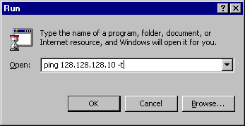
- If you receive a ‘Reply’ then the Ethernet is properly configured. If there is a problem with the Ethernet configuration you will receive a ‘Request Timeout’ message.
- Repeat steps 11-13 using the FARO Laser Tracker IP address: Ping 128.128.128.100 –t.
Connection Problems?
Firewall Blocking Connection of PC and Laser Tracker?
When you are connecting a computer to the FARO® Laser Tracker if the connection drops intermittently or is totally blocked, it may be because corporate firewalls are enabled in your computing environment.
The Laser Tracker may be connected to a computer that is also connected to the internet through a corporate network that is protected by a firewall. If this is the case, contact your IT department to disable any corporate firewall that may be affecting the Tracker,
By default, commands that are sent to the Tracker from the computer are done using FTP through FTP related ports. Data transfer from the Tracker to the computer is done using UDP through Ephemeral (random, unused) ports supplied by the operating system. Tracker SDK version 5.2.0 introduced the ability for an application to use a specific range of ports for data transfer instead of the Ephemeral ports. CAM2 2021.15 and higher provide the ability to use this option when connecting to the tracker through Device Center. Consult the developer for your application for information on this option if you are not using CAM2.
For standard Windows 10/11 operating system installations, rules for the Windows firewall that allow all the applications required to connect to the Tracker should allow proper operation. CAM2 and BuildIT software do create Windows firewall rules for all required applications during their installation. However, the firewall included with older versions of Windows, adding increased security settings than used by the default Windows installation, or 3rd party firewalls may cause problems. If this is occurring, these additional settings need to be disabled.
BuildIT Software Users
BuildIT software utilizes a "Broker" application to communicate with the Tracker. Often communication with this application can be blocked by the Windows Defender Firewall. Its recommend to add this "Broker" application to the list of "Allowed" applications. For more information on this procedure see the applicable article below:
BuildIT Metrology: Connecting to the Vantage Laser Tracker Through a Windows Firewall with BuildIT Metrology
BuildIT Construction: Connecting to the Vantage Laser Tracker Through a Windows Firewall with BuildIT Construction
Reset Ethernet Settings to Factory Default (Vantage S/E)
To perform a “Hard Reset” on your Laser Tracker, it will return your Ethernet settings back to the following factory default settings:
- IP Address: 128.128.128.100
- Subnet Mask: 255.255.255.0
This reset procedure can be useful if the Laser Tracker's Ethernet settings have been changed to use DHCP and there is no network available to connect to the tracker or the it's within an area where Wi-Fi is not allowed. It can also be used if the tracker’s IP address has been changed to something other than the default values and FARO Utilities is not installed on the computer allowing the Find Trackers function to be used.
If the Tracker is currently powered on:
- Push and hold the tracker's power button for at least 30 seconds and then release. The tracker will power down on release of the power button.
- Wait approximately 10 seconds and press the power button once to turn the tracker back on.
- The tracker will take approximately 1 minute to complete its boot up routine. The red lights around the tracker Zenith axis and the red light near the tracker aperture will stop blinking once complete.
- After the tracker has completed its boot up routine, the tracker wired IP address will be set to the factory default settings listed above.
If the Tracker is currently powered off:
- With the tracker power supply connected to the tracker and wall outlet, push and hold the tracker's power button for at least 30 seconds and then release.
- After the tracker has completed its boot up routine, press the power button once to turn the tracker off.
- Wait approximately 10 seconds and press the power button once to turn the tracker back on.
- The tracker will take approximately 1 minute to complete its boot up routine. The red lights around the tracker Zenith axis and the red light near the tracker aperture will stop blinking once complete.
- After the tracker has completed its boot up routine, the tracker wired IP address will be set to the factory default settings listed above.
Note: These procedures can be used on Vantage S/E series trackers that have firmware 2.5.0.2 or higher installed, which would include all units that shipped new or were serviced after December 2018.
Reset Ethernet Settings to Factory Default (Vantage)
In certain situations the wireless transmitter in the Laser Tracker MCU is on, but you cannot connect to the computer or the computer does not have a wireless receiver. In this case you can reset the wireless transmitter and connect using a crossover Ethernet cable. There is a wireless reset button inside the MCU. To press the reset button, you need a thin 0.05mm/0.002in blade.
Use this procedure if the wireless is on, you cannot connect to the computer, or you want to turn the wireless off.
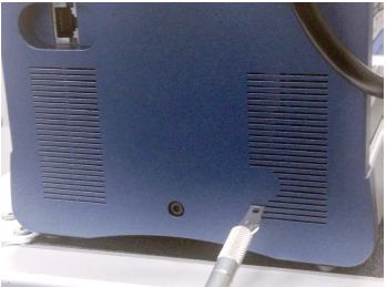
- On the right side of the MCU, locate the ventilation slots. Insert the blade into the left side of the third ventilation slot from the bottom until you depress the reset switch. The Primary and Secondary indicator lights begin to flash when the switch is correctly depressed. Hold the wireless reset button for 1-3 seconds and then release.
- Note: If you have installed the additional filter kit on the MCU to provide it with improved particle protection, the frame for this filter kit may cover up the final bottom ventilation slot.
- Connect a crossover Ethernet cable to the MCU and your computer.
- Start FARO Utilities and click the FIND TRACKER button.
- Right click on the serial number and choose TURN WIRELESS OFF.
- Power off and power on the MCU. Notice the Notice the Primary and Secondary Indicator lights do not flash during the start up.
- Exit FARO Utilities.
- Set the TCP/IP v4 properties of your adapter card (Local Area Connection) to the address of 128.128.128.10.