Setting-Out Points Using the Total Station Interface in As-Built for AutoCAD

Setting-out with As-Built
This article does not explain the ‘Stakeout’ command of As-Built, (this is described in detail in the As-Built user manual). The purpose of this article is to outline the
approach for solving four common tasks of setting-out.
Note: Photogrammetry tools and Total Station support is not available in As-Built for AutoCAD version 2024 and later.
Setting-out Points if Control Points are Available
Source: The architect’s drawing (DWG in 2D) and control points.
Approach: One makes a Free orientation using the control points. Afterwards the points of the drawing are set-out on site using As-Built’s ‘Stakeout’ command.
Setting-out Points if Control Points are Not Available
Source: The architect’s drawing (DWG in 2D), no control points available.
If no control points exist, the as-build-situation must be checked against the plans of the architect.
Approach: One makes a local orientation. Afterwards the as-build-situation is surveyed (not completely but a sample). Then the planned situation is copied form the architect’s drawing into the drawing that contains the as-build-situation.
To do so one uses the AutoCAD commands ‘copy’ and ‘paste as block’. The inserted/pasted block (planned situation) is brought into congruence with the as-build-situation using the command ‘align’. Differences between the architect’s plan and the actual building become obvious. It has to be decided relating to which wall or component of the building the geometry to be set-out has to lie correctly. When this question is answered, the block of the architect’s plan is moved to the appropriate direction if necessary, in order to approximate target and actual situation. Finally, the points of the architect’s drawing are set-out on site using As-Built’s ‘Stakeout’ command.
Setting-out Axes (Batter Board)
Source: The architect’s drawing containing the axes to be set-out (DWG in 2D).
If control points exist these can be used for orientation, otherwise the as-build-situation must be checked against the plans of the architect. To do so one has to do as described in the above section.
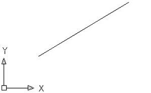
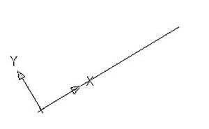
Further approach: Using the adequate AutoCAD command (‘UCS’ plus option ‘ob’) the UCS is aligned with the planned axis. Thus, the direction of the x-axis of the UCS is identical with the direction of the axis to be set-out. At which end of the axis the origin of the USC is fixed and into which direction the y-axis points depends on which end of the line one clicked during its selection. For easier orientation it is recommended to set the display of the UCS icon to the origin (see figure below). If this is not done automatically, one can set it by using the AutoCAD command ‘ucsicon‘ and the option ‘or’.
 |
 |
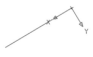 |
| initial situation | line clicked at lower left end | line clicked at upper right end |
Now one simply measures a point with the total station. The command line shows the following prompt:
Command: 20.7788,0.056,3.8976

Unknown command: "20.7788,0.056,3.8976". Press F1 for help.
The second value (the y-coordinate) is the deviation of the measured point from the axis to be set-out. The measurement is repeated until the value of the y-coordinate is zero. If that is the case the point can be marked on site.
Setting-out on a Vertical Wall
Source: The architect’s drawing of a vertical wall (DWG in 2D); the xy-plane of the WCS is the wall; no control points available.
Problem: Orientation within the reference system of the wall is not possible.
If no control points exist, the as-build-situation must be checked against the plans of the architect.
Approach: One makes a local orientation and aligns the x-axis with the existing wall. Afterwards two points are measured in the lower part of the wall. By the help of these points a vertical UCS is defined using the appropriate As-Built command. Now the as-build-situation of the wall’s geometry is surveyed (windows, doors, ceiling…). If the element to be set-out is a window, it is important to measure at least the ceiling within the vertical UCS. If possible the boundary of the wall on its sides and to the ground should be measured as well. If necessary, the measured geometry is flattened into the xy-plane of the vertical UCS. Then the planned situation is copied form the architect’s drawing into the drawing that contains the as-build-situation.
To do so one uses the AutoCAD commands ‘copy’ and ‘paste as block’. The inserted block (planned situation) is brought into congruence with the as-build-situation using the command ‘align’. Differences between the architect’s plan and the actual building become obvious. It must be decided relating to which element the geometry to be set-out has to lie correctly. When this question is answered, the block of the architect’s plan is moved to the appropriate direction if necessary, in order to approximate target and actual situation. Finally, the points of the architect’s drawing are set-out on site using As-Built’s ‘Stakeout’ command. From the ‘Stakeout’ dialogue now only the horizontal and the vertical set-point angle are of use, because the other values (coordinate deviations, longitudinal offset and angle offset) refer to the WCS and not the UCS of the wall.