Creating Topographical Curves with BuildIT Construction
 Objective:
Use BuildIT Construction to create topographical curves.
You’ll learn:
- A simple workflow to create topographic curves.
- Opening a BuildIT file.
- Creating a reference plane
- Use the Topographic Curve tool.
Tutorial Download
If you would like to download the file used in this article, download the accompanying Training Data and extract its contents to a folder on your PC.
Create a Reference Plane
Open the “Garage_scan.buildit” file by selecting “File > Open” and navigating to where the file is saved.
- Select “Refine > Extract Surface”.
- Create a plane from cloud.
- Select the “Fill” option for selecting points.
- Select points with the cursor.
- Ensure “Create new cloud from identified points” is checked.
- Select “Apply”.


Create Topographical Curves
 Now, the analysis will be performed.
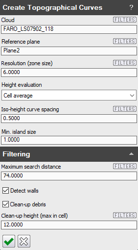
- Select “Evaluate > Floor/Grade Analysis > Create Topographical Curves”.

- Select the Cloud.
- Ensure that you select the main point cloud "FARO_LS0792_118".
- Select the “Reference Plane”.
- Specify a zone size. Use 6 inches for this exercise.
- The zone size is the sampling distance on a grid for the analysis.
- Select Cell average for "Height Evaluation".
- Cell average will create an average reference point from all the points in a cell.
- Low/High Point will create a point from the highest or lowest deviation from reference to represent the cell.
- Center Point will create a point from the point closest to the middle of the cell.
- Enter 0.5 inch for “Iso-height curve spacing”.
- This value represents the detail level of the topography. The lower the number, the finer the difference in topographic height deviation.
- Min. island size
- Minimum island size controls the minimum size of contours. If you run the command and have a high number of small contours, increase the value of minimum island size.
- Check “Detect walls”.
- This setting detects walls in the scan data and ignores them instead of creating curves to represent this cell.
- Check “Clean up debris”.
- Enter 12 inches for “Clean-up height”.
- This controls the maximum point height per cell. This is useful to include then there is extra data in the scan other than the floor.
- Select “Apply”.

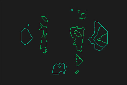
Result:
Note: You can uncheck "Display Object" for the two point clouds and Plane2 to achieve a better onscreen view of the result.

NOTE: The resulting *.dxf file will be automatically saved in the same folder as your saved BuildIT file. Also, there will be text labels of each contour.
Recap:
Congratulations, you have completed the topographical curve creation module! By now you should have a grasp of the following:
- A simple workflow to perform cut/fill volume analysis.
- Opening a BuildIT file.
- Creating a reference plane
- Use the Topographic Curve tool

