                     
As-Built As-Built - Revit As-Built - AutoCAD VirtuSurv - VirtuSurv 2018 As-Built - Modeler VirtuSurv - VirtuSurv 2019          
BuildIT BuildIT - Projector BuildIT - Construction BuildIT - Metrology              
CAM2 CAM2 - SmartInspect CAM2 - 2023 CAM2 - 2018 CAM2 - Measure 10 CAM2 - Measure Q CAM2 - Measure X CAM2 - Measure 3/4 CAM2 - AnthroCAM CAM2 - 2019 CAM2 - 2020
CAM2 CAM2 - 2021                  
Cobalt 3D Imager 3D Imager - Cobalt                  
Cobalt Design Cobalt Design - M Cobalt Design - S Cobalt Design - Dual              
Computers Computers - All Computers                  
FARO Aras 360 & CAD Zone FARO CAD Zone - Fire & Insurance FARO CAD Zone - Crime & Crash FARO CAD Zone - CZ Point Cloud FARO CAD Zone - First Look Pro FARO 360 - Reality FARO 360 - HD FARO 360 - Blitz FARO 360 - Genius    
FARO Connect FARO Connect - Connect                  
FARO Zone present4D - present4D                  
FARO Zone 2D FARO Zone 2D - 2018 FARO Zone 2D - 2019 FARO Zone 2D - 2020 FARO Zone 2D - 2021 FARO Zone 2D - 2022 FARO Zone 2D - 2023        
FARO Zone 3D FARO Zone 3D - 2018 FARO Zone 3D - 2019 FARO Zone 3D - 2020 FARO Zone 3D - 2021 FARO Zone 3D - 2022 FARO Zone 3D - 2023 FARO Zone 3D - 2024      
FARO Zone 3D Advanced FARO Zone 3D Advanced - 2018 FARO Zone 3D Advanced - 2019 FARO Zone 3D Advanced - 2020 FARO Zone 3D Advanced - 2021 FARO Zone 3D Advanced - 2022          
FaroArm/ScanArm FaroArm/ScanArm - Quantum S FaroArm/ScanArm - Quantum M FaroArm/ScanArm - Quantum E FaroArm/ScanArm - Edge FaroArm/ScanArm - Fusion FaroArm/ScanArm - Prime FaroArm/ScanArm - Platinum FaroArm/ScanArm - Legacy Quantum FaroArm/ScanArm - Titanium FaroArm/ScanArm - Advantage
FaroArm/ScanArm FaroArm/ScanArm - Digital Template FaroArm/ScanArm - Gage FaroArm/ScanArm - Quantum S Max FaroArm/ScanArm - Quantum M Max FaroArm/ScanArm - Quantum E Max FaroArm/ScanArm - Gage Max        
GeoSLAM Software GeoSLAM Software - Connect GeoSLAM Software - Draw GeoSLAM Software - Hub GeoSLAM Software - Volumes            
GeoSLAM ZEB GeoSLAM ZEB - Horizon GeoSLAM ZEB - Horizon RT GeoSLAM ZEB - Revo GeoSLAM ZEB - Revo RT GeoSLAM ZEB - Go          
Hand Held Scanner 2D Hand Held Scanner - ScanPlan 3D Hand Held Scanner - Freestyle3D 3D Hand Held Scanner - Freestyle3D X 3D Hand Held Scanner - Freestyle3D Objects 3D Hand Held Scanner - Freestyle 2          
Language Quality HT MT AT NT INT - Internal Sales - Internal Resources Sales - Order and Quote Sales - Product Info Sales - Sales Readiness Sales - Training
Language Quality Sales - Product Launch Sales - Promotions CS - Quote to Invoice CS - Phone System CS - New Hire Training CS - General CS - Product Info CS - Licensing CS - Procedures General CS - Procedures Salesforce
Language Quality CS - Procedures Loaner CS - Procedures SAP                
Languages Language - English Language - Japanese Language - German Language - Chinese Language - Spanish Language - Italian Language - Portuguese Language - French Language - Korean  
Laser Projector RayTracer - RayTracer Laser Projector - Tracer M Laser Projector - Tracer SI              
Laser Radar Imaging Laser Radar - VectorRI                  
Laser Scanner 3D Laser Scanner - Focus S 3D Laser Scanner - Focus M 3D Laser Scanner - Focus3D 3D Laser Scanner - Focus3D X 3D Laser Scanner - Focus3D X HDR 3D Laser Scanner - Focus3D S 3D Laser Scanner - Photon 3D Laser Scanner - Focus S Plus 3D Laser Scanner - Swift 3D Laser Scanner - Focus Premium
Laser Scanner 3D Laser Scanner - Focus Core                  
Laser Tracker Laser Tracker - Vantage Laser Tracker - ION Laser Tracker - Vantage S Laser Tracker - Si Laser Tracker - X Laser Tracker - Xi Laser Tracker - Vantage E Laser Tracker - Vantage S6 Laser Tracker - Vantage E6  
Legacy Gage Legacy Gage - Bluetooth Legacy Gage - Plus Legacy Gage - Standard Legacy Gage - Power            
Legacy Software Legacy Software - CAM2 Gage Legacy Software - Gage Software Legacy Software - Insight              
Mobile Scanner Mobile Scanner - Orbis                  
PointSense PointSense - Basic PointSense - Pro PointSense - Building PointSense - Plant PointSense - Heritage PointSense - Revit CAD Plugin - TachyCAD Building CAD Plugin - TachyCAD Archeology CAD Plugin - TachyCAD Interior CAD Plugin - PhoToPlan Basic
PointSense CAD Plugin - PhoToPlan CAD Plugin - PhoToPlan Pro CAD Plugin - PhoToPlan Ultimate CAD Plugin - DisToPlan CAD Plugin - MonuMap CAD Plugin - hylasFM CAD Plugin - VirtuSurv      
RevEng RevEng - RevEng                  
ScanArm ScanArm - Design ScanArm 2.0 ScanArm - Design ScanArm ScanArm - Forensic ScanArm ScanArm - Design ScanArm 2.5C            
SCENE SCENE - Capture and Process SCENE - WebShare Server and 2Go SCENE - WebShare 2Go App SCENE - 2018 SCENE - 7.x SCENE - 6.x SCENE - 5.x SCENE - 4.x SCENE - LT SCENE - 2019
SCENE SCENE - 2go App SCENE - 2020 SCENE - 2021 SCENE - 2022 SCENE - 2023          
Serial FaroArm Serial FaroArm - Silver Serial FaroArm - Gold Serial FaroArm - Bronze              
Sphere FARO Sphere - Sphere                  
Visual Inspect Visual Inspect - App Visual Inspect - CAD Translator                
WebShare WebShare - Enterprise WebShare - WebShare Cloud                

BuildIT

Projector

FARO® Knowledge Base

Simulate Projection Plans in BuildIT Projector

BuildITProjector-bty.png

Overview

When it comes to setting up physical laser projectors, needs to ensure both coverage and accuracy. Multiple factors need to be taken into account, which are covered in Projector Setup and Tools for Accuracy.

They can now be simulated in BuildIT, at the office rather than on the shop floor. This ensures that once implemented on the production line, there are minimal to no changes needed. This in turn reduces production downtime.

These simulations are also shown to the operator, so that if the planner deliberately outputs a job where not all projections will be visible, there is no mismatch between what is shown in BuildIT and what is being projected.

This article covers the various aspects that can be simulated: Field of View (FOV), Clipping Box, Angle of Incidence, Line of sight obstructions.

ProjectionSimulation.png

In the example above, we see not only green projection lines, but red and grey lines and normal arrows representing various simulated aspects.
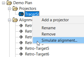
Simulate Alignment

You can simulate the alignment of any projector by right-clicking on it, and selecting Simulate Alignment...

Right-click Simulate Alignment.png

This will open the Manual Alignment command, which allows you to move the Projector around.

ManualAlignment_projector.png

When clicking the Apply button it will update the appearance of the layers. Make sure they are selected in the projection plan to make them visible.

Field of View

As the planner moves the projectors in the 3D view, the projections that fall outside of the FOV will be shown as grey dotted lines.

In the example file, if the Tracer is mounted on the beams right above the part, we can see that some of the projections are just outside of the FOV.

FOV simulation.gif

FOV issues can be rectified by mounting the projectors at a different location and potentially adding more projectors.

Clipping Box

When running multiple projectors with overlapping FOV, each projectors can be limited to a user-specified box to reduce the overlap. If there is no overlap, then the projections that fall outside of any box will show as grey dotted lines.

Projector Clipping box.gif

In this example, it's the grey dotted lines that make it the lack of overlap obvious. Thus a planner can spot them early and fix the issue before sending it to the shop floor.

Angle of Incidence

To minimize the error caused by imperfect surfaces, projections can be clipped if they exceed an angle of incidence. If a projection does not have a small enough incidence angle to any projector, it will show as a grey dotted line with normal arrows.

Angle of Incidence simulation.png

Here the solution is normally to mount the projectors at a different location or to add more projectors. Learn more about how limiting angles of incidence help with accuracy in this article about Projector Setup and Tools for Accuracy.

Obstructions of line of sight

Sometimes the part or tool itself obstructs a projection. Other times, if you are fortunate to have a model of the room you are projecting in, beams and columns may be the culprit. If none of the projectors is able to 'see' a portion of a layer, that portion will show as a red dotted line.

Obstruction Simulation.png