Setting up Projectors for Coverage and Accuracy
Overview
There are many, many factors that should be considered to get the most coverage with the fewest projectors while achieving the desired accuracy. This article goes through each of these factors in increasing level of complexity, with examples and links to helpful articles on related BuildIT Projector capabilities.
Standoff distance
The apex of the projected beam has an angle of 60 degrees. Imagine you want to project on the ground, straight down, and wanted to know how wide the coverage is at 5 meters. To be precise, we can use trigonometry to get:
5m * tan(30 deg) * 2 = 5.77m

If you don’t have a scientific calculator nearby, 2*tan(30 deg) is about 1 so you can rely on this rule of thumb: The side of the projected square is about as long as the stand-off distance.
Whatever size the part is, try to get that standoff distance to get full coverage with just one projector.
If you can place the projector rigidly (minimal vibrations, like on an I-beam) directly above the workspace that would be ideal. However, whether it is due to ceiling height or lack of mounting points that are available, you may not have that luxury. Often, you will need to project at an angle instead.
Projecting at an Angle
In many cases the setup must project from the side. This allows you to get more coverage, where instead of projecting a ~ 5x5 square, we project a trapezoid with much wider sides at the same 5m height, as seen in this view.

If you need additional coverage area, remember that you can also rotate the projector.

Otherwise, if all projections fit within the FOV and range, and from its vantage point it has line of sight for all projections, then your next preoccupation should be accuracy. In the above example, we have drastically increased the distance and incidence angle at the far ends of the coverage area. While this might be a good solution for projecting on to a shaft or long beam, steep angles and long distances reduce accuracy. We must convert the angular accuracy at a given distance, to a projection accuracy for a given grazing angle.
If your environment does not allow you to place the unit far enough from the surface to get full coverage and maintain desired accuracy, then you will need additional projectors.
Accuracy Over Distance
The projector is an angular device, so all inaccuracies are angular. Convert an angular inaccuracy to linear one, and you obtain a distance value that grows over the range of the projection.
The accuracy of TracerM and TracerSI is specified as 0.25mm at 4.6m range. That range is the distance at which we certify our units.
As a rule of thumb, linear error increases proportionally to distance. So, at double the distance (9.2m) you get 0.5mm.
Error Magnification by Angle of Incidence
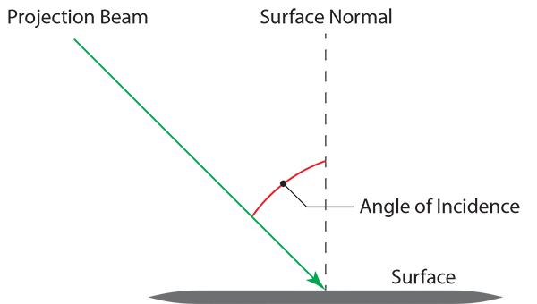
Double distance will double linear error, but this is a projection device and you need to account for the projection plane and the angle of incidence, which magnifies the error.

The error magnified becomes:
linear error / cos(angle of incidence)
So, for example, if the laser beam hits a surface at an incident angle of 30 degrees, 1/cos(30) = 2, which is to say that the error is double what it would be if the beam were perpendicular (90 degrees) to the surface.
Error Due to As-Built Differences
There is yet another source of error, which is caused by the difference between whether the projection surface is expected to be (according to CAD), and where it is in reality (referred to as "as-built"). Since the projector is not a measurement device and is unable to determine the as-built surfaces, there is no way of predicting what the error will be. There is no equation for it.
However, the impact of as-built differences can be mitigated by limiting the angle of incidence of your projection. In the image below, there are two rays aiming at the same point on the CAD with different angles of incidence: The green one, and the red one. Because they land on the as-built surface, they land at different places. The ray with the largest angle of incidence (red) falls much further than the other one (green).

A rule of thumb is to limit the angle to 45 degrees, though for the applications that require highest accuracy it may be limited to 30 degrees.

Any projection that cannot be projected with a low enough angle of incidence will be disabled, and shown as a grey dotted line with arrows showing the local surface' normal direction.

Learn more about how to find the optimal projector setup using BuildIT in this article: Simulate Projection Plans in BuildIT Projector
Multiple Sessions per Projector
For very long parts, multiple projectors are required to project its full length like so:

Keep in mind that a projector can run multiple sessions simultaneously. And so, if two parts fit in that projection space, then they can be assembled simultaneously, allowing you to double your productivity with the same set of projectors:

Alignment Point Accuracy
One last consideration, but not the least, once you have a setup where the projector can realistically provide the coverage and accuracies desired, it is critical that the alignment points are as accurate as possible. Projections cannot be more accurate than the alignment points.
Generally speaking, if you want an accuracy of 1 millimeter you would want the alignment RMS to be no more than one millimeter.

