Plane-lock Scanning for Cross Sections, Threads, or Gears in CAM2
Overview
The Plane-lock scanning option in CAM2 allows you to measure any 2D feature (2D Line, Point, Circle, Slots, and Ellipse) on measured or constructed projection/constraining plane. In other words, you measure or construct a plane, and then slide the probe or Spherically Mounted Retroreflector (SMR) from one side of this virtual plane to another capturing data for the 2D feature.
The Plane-lock scanning method can be used in a variety of applications such as cross section measurements, thread, and gear measurements.
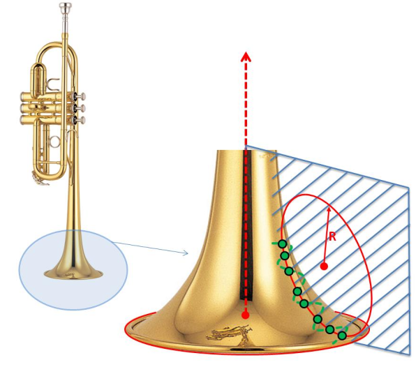
An example is the measurement of the radius (R) of trumpet’s vertical cross section.
Thread Pitch Measurement
Thread pitch is the term used to calculate the difference between two threads. For metric fasteners, thread pitch is used in place of TPI. The distance is also measured in millimeters.
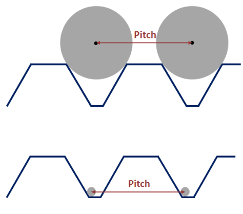
To measure thread pitch, measure from the peak of one thread to the next, as seen below.
When measuring thread pitch, you may also use different probe/SMR sizes, as seen below.
Measuring Thread Pitch in CAM2
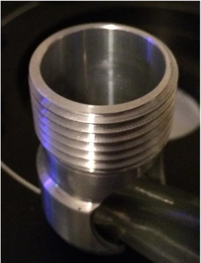
To measure the thread pitch of the part below, use the procedure below as a guide.
Note: Newer versions of CAM2 may look slightly different, but procedurally, everything is the same.
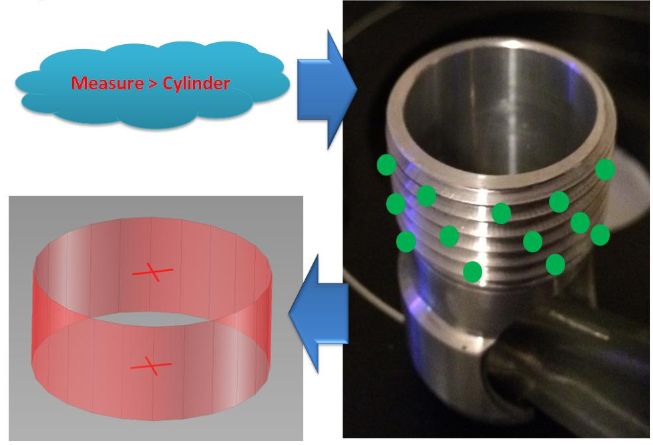
- In the Measure tab, select Cylinder. Measure several points around the cylinder and compensate.
- Measure an additional point (Measure > Point) to be used later in the plane creation needed for this calculation. Note, this is just an arbitrary point outside of the threads that will be used to create a constructed plane from 3 points in Step 5 below.
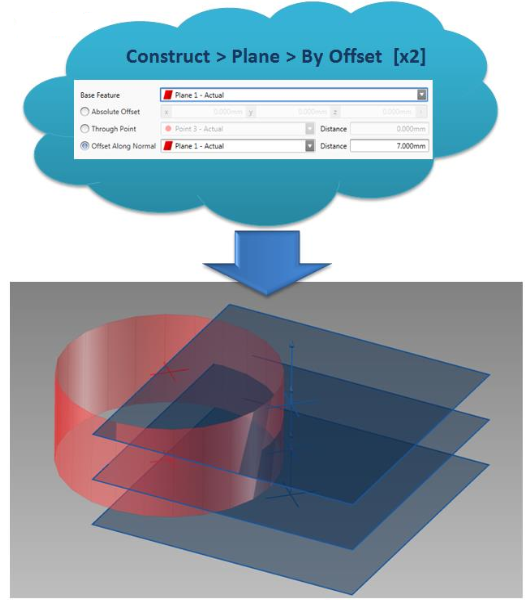
- In the Construct tab, select Plane > By Offset.
- Select Offset Along Normal, set Distance for: 7.000mm
- Click Create. Do this twice.
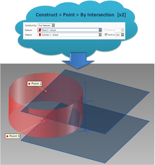
- In the Construct tab, select Point > By Intersection.
- Select Plane and Cylinder.
- Click Create. Do this twice.
- In the Construct tab, select Plane and then By Best Fit.
- Choose 3 points. Click Create.
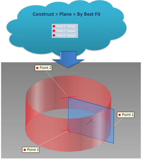
- Choose 3 points. Click Create.
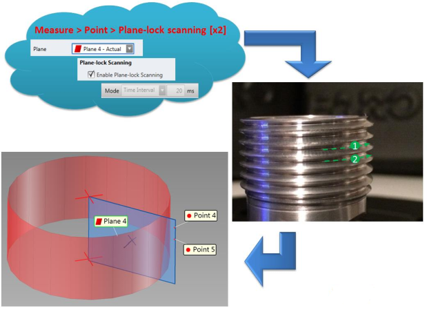
- In the Measure tab, select Other > Planar Point and then click Enable Plane-lock Scanning.
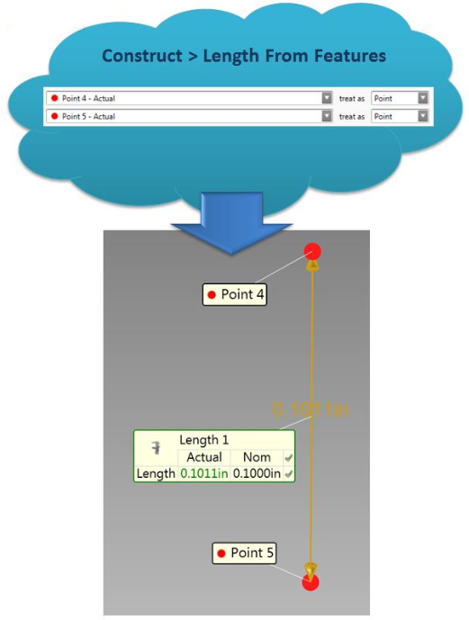
- In the Construct tab, select Length From Features. Select your desired points.
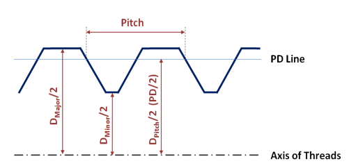
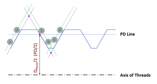
Thread Pitch Diameter Measurement
The probe or SMR should fit into the thread (between the teeth), as shown below.
To measure pitch diameter
- Use the procedure above as you did with Pitch measurement until you construct the Lock-plane.
- Measure three lines using Plane-lock scanning.
- Construct an additional three lines by offset of the radius of the probe/SMR.
- Construct two points by intersection of two pairs of lines (purple dots in image below)
- Construct point by midpoint (red dot in image blow) and dimension from the centerline of the cylinder to this point to get the Pitch Radius.