Release Notes for CAM2
This article lists the Release Notes for each version of CAM2® Software to date. The current version release notes are displayed at the top of the article. Previous revisions are contained in expanding sections below.
Navigating this article:
- Use the Table of Contents block in the upper right hand of this article to jump to a release.
- You can expand a version section by clicking the + button
- To search all versions, click the Expand All Versions button and then use the Ctrl+f search feature in your browser. Sections must be “expanded” to be searched.
CAM2 2026.1 – Release Notes
This CAM2 release includes the following:
Enhancements
1. Korean Language Support / Translations Updated
(All Editions)
CAM2 now supports the Korean language, and supported languages translation have been reviewed and updated.

2. Duplicate Constructions
(All editions)
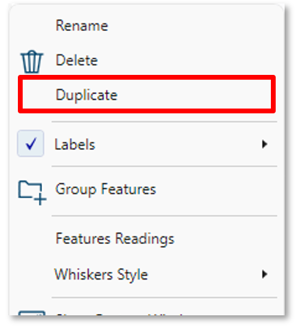
When inspecting a component, the same constructed features may appear in multiple drawing views and must be reflected this way in reports. Users can now duplicate construction using the right‑click Duplicate option, creating a new construction tied to the same features and method as the original.
3. Point Cloud Profile – ‘Click to edit’ indication
(Expert, Scan Professional, Analyst editions)
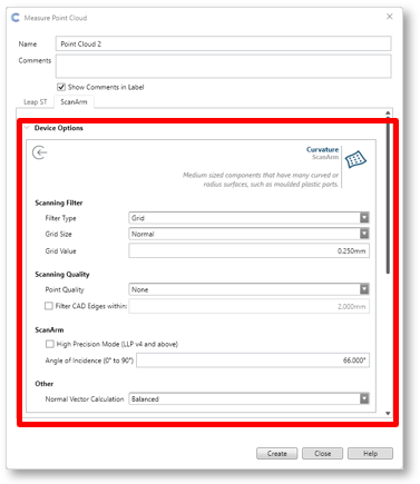
Many users were not aware how to open the Point Cloud Profile to edit the scan settings to be able to create a Custom Profile.
To indicate this, we now display "..." icon when selecting or mousing over a Profile tile.
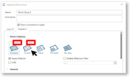
Clicking the "..." icon will open and expose the scan settings, which the user can edit.
4. Best Fit Alignment – Notification Improvements
(Expert, Scan Professional, Analyst editions)
When performing a Point Cloud Best fit alignment, CAM2 compares the volumes of the CAD and Point Cloud and if the volume coverage between the two is less than 80%, we now show an updated notification allowing the user to choose the next actions:
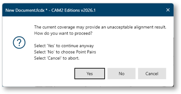
- Select Yes to continue with a Best Fit alignment.
- Select No to enter Point Pairs mode to manually assist the alignment.
- Select Cancel to abort the alignment.
5. Cross Section Feature Extraction
(Expert, Scan Professional, Probe Professional, Analyst editions)
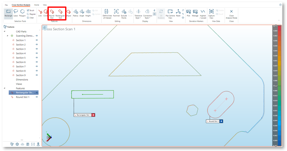
Cross Section Analysis now supports extraction of round and rectangular slot features. A corresponding nominal is automatically created and linked to the extracted feature. When you return to the main workspace, all Cross Section features are organized in a Group Folder.
6. Cross Section Feature Label Support
(Expert, Scan Professional, Probe Professional, Analyst editions)
It is now possible to display labels for extracted features in Cross Section Analysis mode. The label visibility and type can be selected from the right click context menu:

Fixed Issues
Construction
- CAM2M-16213: Constructing Tube from Features does not auto- extract the Tube
Translations
- CAM2M-15548: Coordinate System wizard text is not translated. (always English)
GD&T
- CAM2M-16424: Surface Profile error when using Composite datums.
Preferences
- CAM2M-16376: Extraction Solver Method Preference not working for Vector Points.
Report
- CAM2M-16461: ‘Unable to cast object type...’ error shown when entering Report.
SmartTools
- CAM2M-16454: Length ‘Display Directional Sign’ does not persist in a SmartTool.
CAM2 2026.0 – Release Notes
This CAM2 release includes the following:
3rd Party Component Updates
Hoop Exchange (CAD Translator)
This has been updated to version 2025.9.0 and now provides support to import the the following CAD formats and versions (newly supported versions in red)
Enhancements
1. Extended Creaform Scanner Support
(Expert, Scan Professional)
Users can now use all Creaform device scans directly in CAM2 for alignments, analysis, reporting, and repeat part inspection via QuickTools.
From the Home ribbon, click the Open Creaform OS icon to launch the Creaform Scan application. Capture the required scans, then select Accept Scan to close the application and transfer the data to CAM2.
Note: Creaform OS version 2.1.0.14417 or later is required. Users can access and install the latest Creaform OS release through the Creaform Customer Portal.

2. Cross Section Feature Extraction
(Expert, Scan Professional, Analyst editions)
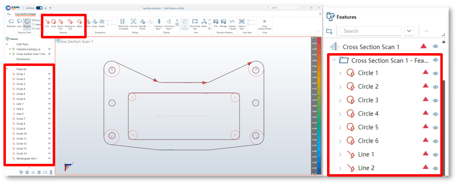
Cross Section Analysis now supports feature extraction using the extraction selection tools. A corresponding nominal is automatically created and linked to the extracted feature. When you return to the main workspace, all Cross Section features are organized in a Group Folder.
3. Point Cloud Color Map – Cad Coloring
(Expert, Scan Professional, Analyst editions)
CAM2 can now show point‑cloud deviations directly on the CAD surface and point cloud together. Enable this under Preferences > CAD View > Point Cloud Settings > CAD Colouring.

4. QuickTools Import Point Cloud step
(Expert, Scan Professional, Analyst edition)
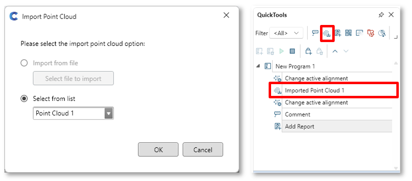
Users can now add an Import Point Cloud step to a QuickTool, allowing them to select an existing Point Cloud from the current fcd/fcdx or from a saved file when running the program. This is especially useful when multiple components have been pre‑scanned, and the same program needs to be applied to each scan.
5. Point Cloud Transparency
(Expert, Scan Professional, Analyst edition)
Users can now adjust Point Cloud transparency directly from the feature properties.
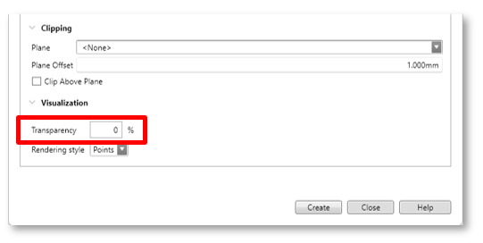
Note: Transparency is removed when color map is shown.
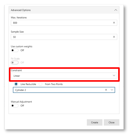
6. Iterative Alignment Linear Constraint
(Expert, Scan Professional, Probe Professional, Analyst edition)
In Iterative Alignment’s Advanced options, users can now apply a linear constraint by selecting a line‑reducible or two‑point‑reducible feature from the drop‑down list.
7. Duplicate Dimensions
(All editions)
When inspecting a component, the same length or angle may appear in multiple drawing views and must be reflected in reports. To streamline this, users can now duplicate a dimension using the right‑click Duplicate option, creating a new dimension tied to the same feature as the original.

8. Feature List Search
(All editions)
The new search bar at the top of the Feature List allows users to filter features by category or text.
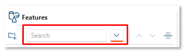
Note: Features stored in Group Folders are not currently searchable.
9. Feature List Insert – Group Folder Support
(All editions)
The Insert option now lets users expand a Group Folder and choose an exact insert position. New features are added to the folder at the selected location.

Fixed Issues
Height Gauge Mode
- CAM2M-15344: numbers displayed are removed when arm is in the rest position.
License
- CAM2M-16423: InTouch auto updates to 2026 regardless of license validity (hotfix 12.9.439)
Measurement
- CAM2M-16233: CAM2 takes readings without triggering it. (Distance based)
Ribbons
- CAM2M-16070: Pick Deviation icon not available in View ribbon.
- CAM2M-16163: Pick Deviation icon not available in View ribbon.
Support Data
- CAM2M-16265: Generated support data_ all log files have the same modified date.
QuickTools / Image Creator
- CAM2M-16231: Crash when using QuickTool with Guidance Images enabled
- CAM2M-16301: Crash when using QuickTool with Guidance Images enabled
CAM2 2025.7 – Release Notes
This CAM2 release includes the following:
Technology Updates
.NET 8 Update
CAM2’s runtime technology has been updated to .NET 8, which brings performance, stability and security improvements.
Driver Updates
The FaroArm driver has been updated to 6.11.77.
3rd Party Component Updates
Hoop Exchange (CAD Translator)
This has been updated to version 2025.7.0 and now provides support to import the the following CAD formats and versions (newly supported versions in red)
Enhancements
1. Foremost Facing enhancements
(Expert, Scan Professional, Analyst edition)
The Foremost Facing selection option is now available for use when selecting data from Feature Extractions:

and when selecting data in the Point Cloud workspace.

2. Point Cloud Scanning Profile Improvements
(Expert, Scan Professional, Analyst edition)
When scanning with a grid filter applied, e.g. using Curvature, Smooth, Detailed or Fine detailed profiles, improvements have been implemented to remove overlapping data, and maintain the best quality data per grid.
In addition, the Full profile has been renamed Raw, to better indicate that this captures all data provide by the LLP, and no filters or overlap removal are applied.

Note: We recommended to always use a grid filter when scanning to avoid capturing unwanted duplicate data, which can significantly increase the point cloud size, which could affect performance.
3. Search Bar
(All Editions)
We have implemented a context search bar to assist users to search and find operations that are available within the workspace or mode that they are currently in. This can be found to the right-hand side of the title bar:

Simply start typing the name of the required operation, for example ‘Align’ and the search bar will offer all available options to select from:

4. Creaform OS: Menu strip
(Expert & Scan Professional Editions)
When opening Creaform OS from the CAM2 ribbon, the Menu strip options are now available, allowing users to access the File, Configure and Help options.

5. Create features from Targets using Manual Probing
(Expert & Scan Professional, Analyst Editions)
CAM2 now allows users to create features by manually picking targets using Extract > Manual Probing > Pick Readings capabilities.

As targets are selected and highlighted, the available features are shown in the right-hand bar. Simply select the required feature to create it.

The created features can then be use as any other feature for co-ordinate systems etc.
Note: users must hide the data type they do not want to use. e.g. to only use targets, hide the Point Cloud, and vice versa.
6. QuickTools: Create from Features support for handheld scanners
(Expert & Scan Professional, Analyst Editions)
If an inspection routine already exists in the Feature list, using Creaform OS or Leap Capture, it is now possible to create a QuickTool by simply selecting Automation > QuickTools > Create from Features.

This will copy the required measurement step into the QuickTool panel.
Fixed Issues
Application
- CAM2M-16267: Exception Info: System.Net.Http.HttpRequestException (hotfix v12.8.333)
- CAM2M-16170: Exception when closing Probe Professional & Essentials (hotfix v12.8.328)
Alignment: Manual Adjustment
- CAM2M-16122: It’s not possible to enter a rotation angle less than 0.1°
CAD translator
- CAM2M-13554: It’s not possible to Import a specific Step cad file
- CAM2M-15983: It’s not possible to Import a specific SLDPRT 2025 cad file
Construction
- CAM2M-15889: Exception displayed: construct Plane by offset from Torus
Feature Information
- CAM2M-16202: Incorrect form values if units are not millimeters. (hotfix v12.8.332)
File
- CAM2M-16068: Unable to open specific fcdx file
Labels
- CAM2M-15341: Random disappearing cell lines in labels
Measurement Data
- CAM2M-16201: Incorrect values displayed if units are not millimeters. (hotfix v12.8.332)
Pick from CAD
- CAM2M-15812: Vector point direction inverted compared to mesh surface
QuickTools
- CAM2M-13631: 3 x Change Active Alignments steps added instead of one
Tolerances
- CAM2M-13567: DIN ISO & DIN: lower and upper tolerances are incorrect
Ribbon
- CAM2M-16175 : Foremost Face icons not visible in Scan Professional (hotfix v12.8.330)
Registration
- CAM2M-14220: After merging registration groups, viewer does not update
CAM2 2025.6 – Release Notes
This CAM2 release includes the following Enhancements and Fixed Issues.
Enhancements
1. Creaform HandySCAN Black Elite Support
(Scan Professional, Expert)
Users now can utilize their Creaform device scans directly in CAM2, to perform alignments, analysis, reporting and repeat part inspection using QuickTools.
From the Home ribbon, select the Open Creaform OS icon, to open the Creaform Scan application:

The Creaform scanning application will open, allowing users to capture their required scans.

Once the scan is complete, selecting the Accept Scan icon will close the Creaform application and transfer the scan data to CAM2.

The transferred scan can now be used for alignments, feature extraction etc.
Fixed Issues
CAD View
- CAM2M-15833: Colour Scale does not match custom tolerance.
Labels
- CAM2M-15748: Labels from defined Capture Views in QuickTools not positioned correctly
Preferences
- CAM2M-15890: Checkbox for ‘Show tactile probe/laser line’ is not working properly.
Temperature Compensation
- CAM2M-15244: Nominals change after applying CTE & Temperature if new CS is created.
CAM2 2025.5 – Release Notes
This CAM2 release includes the following Enhancements and Fixed Issues.
Enhancements
1. Point Cloud Properties – Align to and Compare to options
(Expert, Scan Professional & Analyst editions)
To further enhance the Point cloud capabilities, CAM2 now provides users the option to align to one CAD model but compare to another (color map). This is particularly useful in Casting inspection workflows where users need to align to an ‘as cast’ model’, but compare the scan to an ‘as machined’ model, to assess if there is enough excess material needed for the machining process.
The Point Cloud properties now have 2 options:
- Align to – this determines which reference item is used for the Point Cloud alignment (Best Fit or Iterative alignments)
- Compare to - this determines which reference item is used for the deviation comparison (color map).

Note: It is recommended that the ‘Align to’ CAD model is hidden to enable the color map to be visible when using different models.
2. Iterative alignment (Point Cloud) – Manual Adjustment
(Expert, Scan Professional & Analyst editions)
To further support customer workflows, such as Casting Inspection, it is now possible to manually adjust a Point Cloud iterative alignment, by entering offsets and/ or rotations in X, Y and Z.
From the Home or Alignments ribbon:
- Select Manage to open alignments manager.

- Select the required alignment in the left-hand list.
- Expand the Advanced Options
- Toggle on the Manual Adjustment option. The manual adjustments options will now be shown:

- Translation – enter the requirement distances into the X, Y Z cells to translate (offset) the alignment in the required directions.
- Rotation – enter the requirement angles into the X, Y Z cells to rotate the alignment around the required axis.
- Center of Rotation – enter the X, Y Z position to be used for the rotation adjustments. By default, the origin (0,0,0) is used.
- Select Modify to update the alignment using the entered values.
Note: Supports Iterative alignments that contain Point Cloud only.
3. Construct by Best Fit – solver methods added
(Expert, Probe Professional, Probe Essentials & Analyst editions)
We now allow users to select the solver method when constructing a feature by Best Fit using Feature Readings.
A typical use case is where a user requires that a measured hole diameter be reported using Standard (best fit), Minimum and Maximum fit results. Users can now simply Construct by Best Fit another Feature using the readings of existing measured features and apply the required solver method.
When the original feature is remeasured, the constructed features will automatically recalculate.

Note: the use of extracted features is not supported.
4. Sensitivity Sliders added to automatic selection tool
(Expert, Scan Professional & Analyst editions)
To provide users more control when using the Connected, Disconnected and Outliers selection tools, we have added sensitivity slider that when changed will select either more or less data based upon the level chosen. The slider will be available by selecting the settings icon displayed in the top left-hand corner of the Viewer.

Once the slider position is changed, the selection will be recalculated.
Connected Data:
- Increasing the level (+) will reduce the number of points selected as the allowable distance between point bodies is reduced.
- decreasing the level (-) will increase the number of points selected as the allowable distance between point bodies is increased.
Disconnected Data:
- Increasing the level (+) will increase the number of points selected as the allowable distance from the main scan body to large clusters of points is reduced.
- Decreasing the level (-) will decrease the number of points selected as the allowable distance from the main scan body to large clusters of points is increased.
Outliers:
- Increasing the level (+) will increase the number of points selected as the allowable distance from the main scan body to small clusters of points is reduced.
- Decreasing the level (-) will decrease the number of points selected as the allowable distance from the main scan body to small clusters of points is increased.
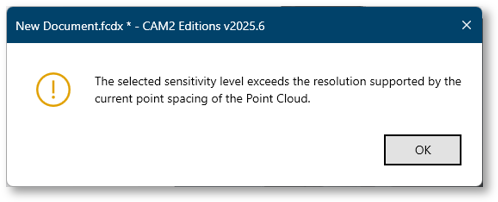
In some cases it may not be possible to increase the selection level due to the point spacing, and in this situation a notification will be displayed.
5. Point Cloud: Protect Data
(Expert edition)
This capability allows users to ‘Protect’ a selected area of an existing Point Cloud, so that when a user adds readings or edits the data, the protected areas will not be changed.
A typical example is if a user needs to clamp the part at various positions during scanning but also needs scan the surface being held / clamped, to achieve a full scan of the component, after deleting the previously scanned clamp area of the Point Cloud.
- From the Measure ribbon Scan Editing group, select the preferred selection tool and select the area of Point Cloud to be protected.
Note: We have implemented a new Foremost Face selection option, which will only select data on the visible surface, and not data behind. (This is not the same a Front Facing which will select any surface facing the user regardless of visibility)
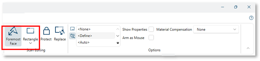
- Then toggle on Protect which now be enabled, and the selected area will change to an aqua blue color.
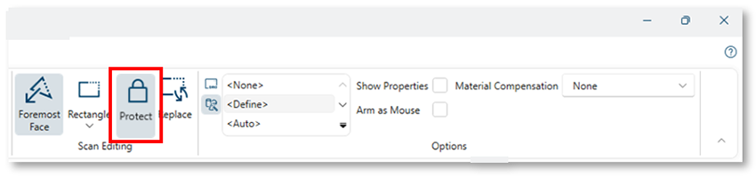
It is now possible to add readings to the Point Cloud. Then select and delete unwanted data from the Point Cloud, however the protected selection will remain unchanged.
- To remove the protection, simply toggle off the Protect option, and the Point Cloud color returns to grey and is no longer protected:

6. Point Cloud: Replace Data
(Expert edition)
This capability allows users to ‘Replace’ a selected area of an existing Point Cloud. A typical example is if a user has scanned a component which a larger point spacing, but requires much finer resolution only in certain areas, for example part markings.
- From the Measure ribbon Scan Editing group, select the preferred selection tool and select the area of Point Cloud to be replaced.
Note: We have implemented a new Foremost Face selection option, which will only select data on the visible surface, and not data behind. (This is not the same a Front Facing which will select any surface facing the user regardless of visibility)

- Then select Replace and the selected area will change to a magenta color and a panel will open to allow the user to select the Point spacing prior to rescanning.

- Enter the required Point spacing and then click Continue and rescan the selected area.
- Scan the selected area and once ended, the rescanned area will change color back to grey.
The selected area will now display the data captured at the new point spacing.
7. Target Registration
(Scan Professional, Expert & Analyst editions)
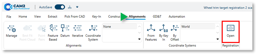
This capability allows users to register multiple scans using common targets, typically required in situations where it was not possible to capture the whole Target Network / component in a single scan.
- From the Alignment ribbon Registration group, select Open, to enter the Registration mode.
From the Point Cloud Registration ribbon:
- Select the Data Type from the first dropdown.

This determines which data type is used for the registration.- Both – allows Point Pair picking on Point Cloud and Targets.
- Point Cloud – allows Point Pair picking on Point Cloud only.
- Targets – allows Point Pair picking on Targets only.
To use targets for registration, select either Both or Targets as the Data Type, then:
- From the Point Cloud list, select a Static Point Cloud. This remains fixed in its original position during registration.

- From the Point Cloud list, select a Moveable Point Cloud. This will move to the Static Point Cloud position during registration.
- From the Point Cloud list, select a Moveable Point Cloud into the right window.

If targets exist on both selected scans, select Preview to preview the auto registration which uses 3 matching targets from each scan. - The auto selected targets are highlighted in the left window.

If the registration looks visually correct:
- Select Register from the ribbon. This will create a Registration Group, and the Moveable Point Cloud is displayed registered in the Static window.
The initial registration accuracy is shown in the lower right corner.
Note: The accuracy values is the max error between the Point Clouds not the targets, but this is not the final registration result.

Note: The accuracy values is the max error between the Point Clouds not the targets, but this is not the final registration value yet.
At this stage, it is possible to refine the registration by:
- Selecting the Registration Group in the list
- Then selecting Fine Registration from the Ribbon

The final registration accuracy is shown in the lower right corner. The previously detailed steps can be repeated for all scans that require registration.
Once all scans are fully registered, select Close from the ribbon to return to the main Features workspace.
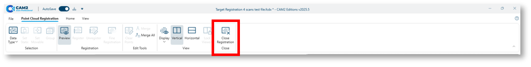
In the unlikely event that the auto registration method using targets fails, it is possible to manually register by selecting Point Pairs on targets in the same way as is possible for Point Cloud.
8. Dynamic Reading Size: ScanArm
(Expert edition)
When enabled, the Dynamic Resize Point Cloud Readings preference will adjust the Point cloud readings size automatically based upon the grid size used during scanning, to provide a surface like visualization as the suer zooms in.
The preference is enabled by default and can be found in Preferences > Display > CAD View > Size and Scale.
Note: When this preference is enabled, the manual Reading Size slider will not change the Point Cloud readings size.
9. Hide CAD & Features when scanning Point Cloud
(Expert edition)
In some cases, when no alignment is active, imported CAD model and created features can obstruct the users view while scanning Point Cloud during the measurement process.
To improve user experience, we have implemented a Hide Feature & CAD when measuring Point Cloud preference located at Display > CAD View > Measurement.

When enabled, this will hide everything other than the Point Cloud being measured, but only if there is no active alignment.
10. Updated translations
(All editions)
All supported languages have been reviewed and updated following addition of new development.
Fixed Issues
Conflict with Measure 10 installation
- CAM2M-15802: Conflict with file location and version when Measure 10 is also installed.
Coordinate System Manager
- CAM2M-15173: World’ is not present in ‘Align with’ dropdown.
DRO
- CAM2M-15354: DRO values incorrect for Single Point Circles.
Labels
- CAM2M-15243: Unable to show Tube Breakpoint labels.
Measurement Window
- CAM2M-15549: Geometric data is not shown if Guidance Image is enabled.
Report
- CAM2M-15424: Operator field is empty in Document Header information.
SmartTools
- CAM2M-15571: 5 PCD & Angles SmartTool does not create the expected features.
CAM2 2025.4 – Release Notes
This CAM2 release includes the following Driver Updates, Enhancements and Fixed Issues.
Driver Updates
FaroArm Driver
FaroArm driver updated to version 6.11.21.
Enhancements
Additional Options for Custom Tolerances Color Schemes
Users now have additional custom tolerance settings when creating custom tolerance color schemes to allow more control of the number of colored intervals used during comparison.
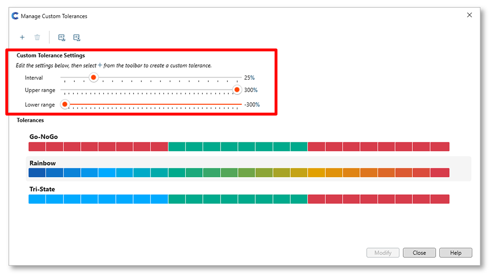
- Interval: number of the colored segments based upon the selected percent of tolerance interval.
- Range = 10% > 100% intervals
- Upper range: the upper percent of tolerance to be colorized.
- Range = +100% > +300 % at intervals of 5%
- Lower range: the lower percent of tolerance to be colorized.
- Range = -100% > -300 % at intervals of 5%
Directional Sign Option for X, Y, Z Lengths
When creating the lengths between features the ‘Display directional sign to X,Y,Z’ option will indicate the direction between the first and second feature, relative to the active coordinate system, when checked.

This capability is useful in certain workflows, such as Roller Alignment, where users need to compare the fixed end point to an adjustment end point of a cylinder, relative to the active coordinate system.
The coordinate system is typically set by the main drive rollers, and by checking the end points of subsequent rollers using the Directional Sign option, users can understand how much to adjust the rollers in each direction, to ensure this are parallel to the main drive roller.
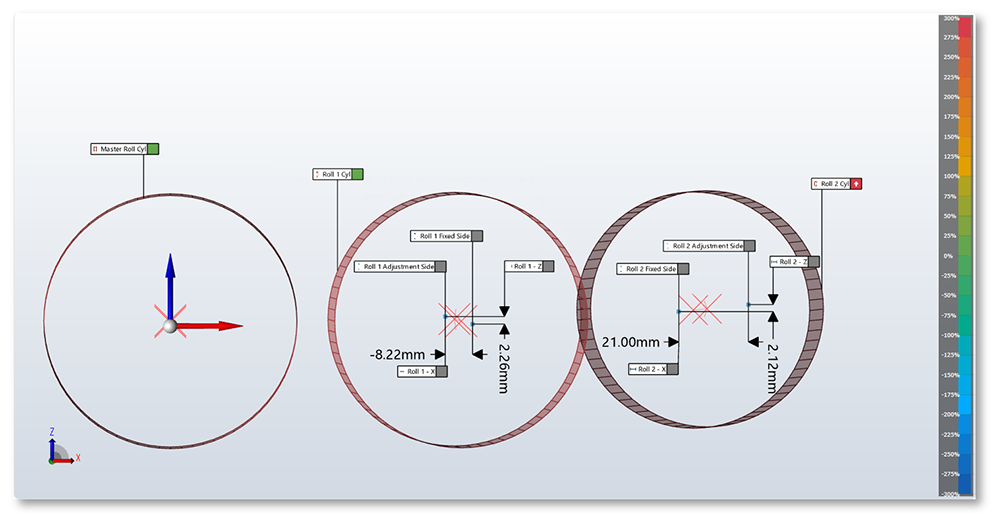
NOTE: When this option is enable only a ‘-‘ sign is shown if the length is in the negative direction of the coordinate axis, e.g. -8.22mm. Any positive direction will have no sign prefix e.g. 2.26mm.
Cross Section Analysis – View Enhancements
To improve user experience, when in Cross Section mode, it is now only possible to rotate the view in 2D. To complement this change we have implemented a new option Flip Camera View, which when selected will display the view from the opposite side of the cross-section plane.

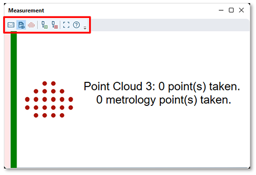
Point Cloud Measurement Window Improvements
To improve user experience, when measuring a Point Cloud, we have removed options that are not applicable to Point Cloud from the Measurement Window toolbar:
Fixed Issues
CAD Translation
- CAM2M-15315: Cannot import Parasolid file created in Inventor 2025.
Export
- CAM2M-15333: Export Data to Text File doesn’t respect the user defined decimal places.
Extraction
- CAM2M-15323: Extracting a Plane using maximum solver is using the minimum solver.
File
- CAM2M-15314: Saving a file as .fcdx saves as a .fcd file in non-English languages.
Group Folders
- CAM2M-15371: Deleting multiple readings from Group Folder doesn't delete the readings.
Labels
- CAM2M-15163: Labels are too big when switching to Cross-Section Analysis Mode.
Measurement Data Panel
- CAM2M-15323: Unable to select readings to show/hide whisker deviations using lasso.
CAM2 2025.3 – Release Notes
This CAM2 release includes the following Enhancements and Fixed Issues.
Enhancements
Cross Section Analysis available in Probe Professional
Users can measure Cross Section Scans using a hard probe; however, Cross Section Analysis mode was not available. We have now added Cross Section Analysis mode to the Analysis group within the Home ribbon so users can perform analysis on their hard probed cross sections.

Fixed Issues
Extraction
- CAM2M-15153: Vector Point doesn’t extract automatically in user file.
Feature Rendering
- CAM2M-14740: When measuring a partial torus it is being rendered as a full torus.
Image Creator
- CAM2M-15246: the Reading Inside / Outside icons in the ribbon are reversed.
Measurement
- CAM2M-15087: Calculation error with Torus form.
- CAM2M-15160: Incorrect values displayed in Height Gage.
Registration
- CAM2M-13740: When picking point pairs, the point position changes.
Report
- CAM2M-15247: Cannot open file if a Custom Tolerance file name has special characters.
Migrated SmartInspect Files
- CAM2M-15238: Probe Essentials: Unable to open files (duplicate device positions)
CAM2 2025.2 – Release Notes
This CAM2 release includes the following Enhancements and Fixed Issues.
Enhancements
Point Cloud Mode: Automatic Data Selection Tools
(Scan Professional, Expert and Analyst editions)
We now provide users 3 Automatic Data Selection tools, to help aid the cleaning and editing of Point Clouds, located in the Home ribbon of the Point Cloud Mode.

Connected Data
This option will automatically select connected data based upon a user cursor click on the Point Cloud:
- A single cursor click on the point cloud, and CAM2 will select all data deemed to be connected.
- Select multiple areas by holding the <SHIFT> key while clicking with the cursor.

- Deselect multiple connected area by holding the <CTRL> key while clicking with the mouse cursor.
Disconnected Data
This option will automatically select data that is disconnected from the largest body of scan and does not require any user click after enabling the option from the Toolbar.

Outliers
This option will automatically select isolated point or small groups of data and does not require any user click after enabling the option from the Toolbar.
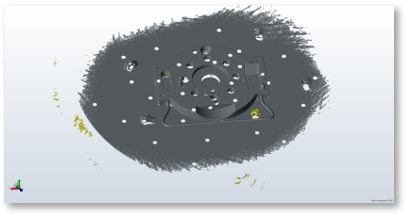
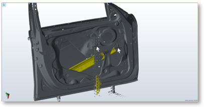
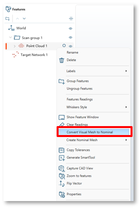
Convert Visual Mesh to Nominal Mesh
(Scan Professional, Expert and Analyst editions)
It is now possible to convert the Point Cloud visual mesh, to a nominal mesh. This allows users to use this as a reference (CAD) or to further process in RevEng or other meshing applications.
Prerequisites: A scanned Point Cloud must have previously had the visual mesh created. (Point Cloud Properties > Visualization >Rendering Style > Mesh)
Then from the Features list, simply select the Point Cloud, right click and select Convert Visual Mesh to Nominal. The mesh will be saved into the same location as the fcd/fcdx file and imported into CAM2 as a CAD reference (colored gold).
QuickTool Support for Scan Professional and Leap Capture Scans
(Scan Professional and Expert editions)
It is now possible to create QuickTools in Scan Professional, that include a step to open Leap Capture and allow the user to perform their scans, as part of a repeat inspection workflow. The Automation ribbon contains the available QuickTool commands.
When included in a QuickTool, a Leap Capture Scan step will open Leap Capture, blocking the CAM2 UI, to allow users to perform the required scans.
A Leap Capture step can only be added into a QuickTool by using the ‘Record’ option.

Once the scans are complete, clicking the CAM2 icon in Leap Capture will trigger the CAM2 QuickTool to retrieve the scan data, and use this to replace any existing Target Network and Point Cloud data.
Any subsequent QuickTool steps, such as alignments, extractions, cross section and reports, will then be automatically calculated,
Note: RPM currently does not support Leap ST or Scan Proffesional QuickTools.
Report: Target Network support
(Scan Professional, Expert and Analyst editions)
It is now possible to include Target Network onto a report, where the position of each target will be displayed in a table:

Labels: Connector Line Style Customization
(All editions)
Users can now customize the label connector line style via the Labels Preferences:

Fixed Issues
Construction
- CAM2M-13847: Cross Section: Deviation Markers only appear in small area of the section.
- CAM2M-15085: Cross Section: CAM2 takes too long to generate if using a large STL as CAD.
Ribbon
- CAM2M-15060: Clear Reading icon missing from Probe Professional Home ribbon.
CAM2 2025.1 – Release Notes
This CAM2 release includes the following Enhancements and Fixed Issues.
Enhancements
Label Connector Customization (applies to all CAM2 editions)
Users can now customize the label connector line color and thickness via the Labels Preferences:

Active Coordinate System Visual Indication (applies to all CAM2 editions)
When users create multiple Coordinate Systems, all non -active Coordinate System triads will be displayed with transparency in the 3D viewer, so that the active Coordinate System triad is more prominent.

Fixed Issues
Construction
- CAM2M-12830: The intersection point isn’t positioned correctly on the torus surface.
Extraction
- CAM2M-15036: Torus extraction from concaved surface provides incorrect results.
Viewer
- CAM2M-13813: Grid disappears after rotating using default 2d views
CAM2 2025.0 - What’s New?
For 3D metrology customers, CAM2 is a robust, intuitive, and highly modular software solution that integrates all the essential functionalities required for 3D measurement operations into a single, seamless ecosystem. This all-in-one platform streamlines workflows, enhances accuracy, and adapts to diverse operational needs, empowering users to perform comprehensive measurements and inspections with ease and efficiency.
CAM2 2024.9 – Release Notes
This CAM2 release includes the following Updates and Fixed Issues.
Enhancements
FaroArm Manager
The FaroArm Manager has been updated to version 6.11.15, and now includes manuals for all supported languages.
CRITICAL NOTE: CUSTOMERS MUST UPDATE TO THIS VERSION OF DRIVER AS THE PREVIOUS DRIVER (6.11.13) WAS TIME LIMITED, SO WILL CEASE WORKING ON 1ST JANUARY 2025.
Licence Manager 2.1
The FARO Licensing Manager provides a single interface to manage all your FARO software licenses from one convenient application. Activate a new license, manage and update licenses, and view active maintenance plans/expiration dates.
- Licenses (home screen) - Displays all licenses currently installed on the computer. Each listing includes the expiration date and other related information. A filter can be used to narrow the licenses displayed and the settings panel allows to change the license selected to run FARO applications.
- Activate - Allows entry of a product key for activation of a new license.
- Configure - Provides basic settings to configure network license servers or clients.
- Notifications - Opens the Notification pane. The notification pane lists newly activated licenses, expired licenses, and update license results.

Notifications
The notifications pane contains a historic view of licensing-related activities. Clicking on any notification will display a pop-up window with additional details.
 |
Listed below are some of the most common notifications:
|
Fixed Issues & Improvements
Report
- CAM2M-14685: Selecting Include Overall Status button opens Report Designer
Ribbons
- CAM2M-14803: Some Import /Export options not available in ribbon customisation.
CAM2 2024.8 – Release Notes
This CAM2 release includes the following Enhancements and Fixed Issues.
Enhancements
New FARO Quantum X Model Support
CAM2 provides support for the new FaroArm models, Quantum X.S, Quantum X.M and Quantum X.E. Once connected to the PC, Device Center will automatically detect and make the device available for use in CAM2.
Fixed Issues
Extraction
- CAM2M-13916: After turning off CAD comparison, extracted features become ‘unsolved’.
CAM2 2024.7 – Release Notes
This CAM2 release includes the following Fixed Issues.
Fixed Issues
Capture CAD View
- CAM2M-13454: Label positions incorrect when assigning a CAD View for a QuickTool step.
- CAM2M-13778: Label positions incorrect when a CAD View is assigned to a QT comment step.
Feature Information
- CAM2M-14237: Nominal values change after entering when Spherical Coordinates are used.
Import Image
- CAM2M-14432: Error shown when importing the same image twice.
Point Cloud
- CAM2M-13485: Incorrect Form / Surface Profile values when a Point Cloud is aligned to CAD.
- CAM2M-14357: Crash after measuring Point Cloud using live mesh rendering.
Ribbon
- CAM2M-14493: Ribbon customization menu issue addressed.
CAM2 2024.6 – Release Notes
This CAM2 release includes the following Enhancements and Fixed Issues.
Enhancements
FaroArm Driver Update
The FARO Arm Manger has been updated to version 6.10.55.
Point Cloud Properties - Mesh visualization
Users can now to choose the visualization method of each point cloud, either before or after capture, by selecting the required Rendering style under the Visualization section of the Point Cloud Properties.

Note: Selecting the Mesh rendering style prior to scanning, will then display live mesh as the data is captured, and after scanning is complete, the point cloud mesh will be recalculated to refine the live mesh. The progress line is shown underneath the Point Cloud in the Feature list:

Fixed Issues
Deviation Markers
- CAM2M-13559: Deviation markers not being created with customer file / CAD.
Device Position
- CAM2M-14247: Unable to create a new device position using more than 11 features.
Export CAD
- CAM2M-14104: Features incorrectly positioned when exporting to Step format.
Note: to correct previously exported .step files, please repeat the export operation using CAM2 2024.6.
Image Creator
- CAM2M-14119 : Imported images are not shown in QuickTool using French language.
Registration
- CAM2M-13743: After performing registration the viewer does not update to visualise results.
CAM2 2024.5 – Release Notes
This CAM2 release includes the following Fixed Issue.
Fixed Issues
Coordinate Systems
- CAM2M-13369: Unable to select point-reducible features when creating a Plane - Plane CS
CAM2 2024.4 – Release Notes
This CAM2 release includes the following Enhancements and Fixed Issues.
Enhancements
Hoop Exchange (CAD Translator)
This has been updated to version 2024.3.0 and now supports the following CAD formats.
Fixed Issues
Import CAD
- CAM2M-12936 : Error occurs when trying to import a CAD file (.sab extension).
Import Points
- CAM2M-14014: Importing ‘actual’ points from file are not rendered in the correct position.
Lengths
- CAM2M-13533: 2D Length display is not updated relative to the active coordinate system.
Whiskers
- CAM2M-13810: Deviation not always shown when mouse hovering over a whisker.
Reporting
- CAM2M-13094: View data are not automatically updating on the report.
Device Center
- CAM2M-14031: Device card always shows ‘No probe attached’ (legacy FaroArm)
RPM
- CAM2M-13598: RPM not respecting the decimal places the document was published with.
CAM2 2024.3 – Release Notes
This CAM2 release includes the following Fixed Issues.
Fixed Issues
Construction
- CAM2M-13270 : Plane by best fit calculated size incorrect based on selected features.
- CAM2M-13837: Plane by best fit display size / orientation incorrect based on selected features.
Feature List
- CAM2M-13738 (1) : DRF with more than 1 datum letter are overlapping.
File
- CAM2M-13870: Unable to open file with ‘Read Only’ file property enabled.
Installation
- CAM2M-13242: Installation fails if Nvidia profile cannot be written to PC (using non-Nvidia GPU).
Measurement
- CAM2M-13736: Delay when measuring Plane lock feature if using a legacy Faroarm (e.g. Fusion).
- CAM2M-13883: Cannot measure consecutive Point Clouds if ‘Show Control Window’ is enabled.
- CAM2M-13934: Crash when selected ‘Clear All Readings’ in customer file.
Preferences
- CAM2M-13562: Exception caused when Construction > Include ancestry types = Measured.
Report
- CAM2M-13738 (2) : DRF with more than 1 datum letter are overlapping.
CAM2 2024.2 – Release Notes
This CAM2 release includes the following 3rd Party Component Updates, and Fixed Issues.
3rd Party Component Updates
Hoop Visualize (Viewer)
This has been updated to version 3DF 29.00.
Fixed Issues
Alignment
- CAM2M-13535: Imported actual points do not visually move after iterative alignment.
Measurement
- CAM2M-13728 : Crash when measuring > 1000 Inspect Surface Points.
Vector Points
- CAM2M-13694: Rectangular zone rendering does not match vector direction in customer file.
CAM2 2024.1 – Release Notes
This CAM2 release includes the following Enhancements and Fixed Issues.
Enhancements
Hoop Exchange (CAD Translator)
This has been updated to version 2024.1.0 and now supports the following CAD formats.
Point Cloud Properties Updated
The Point Cloud Properties window has been updated, resulting in the content being reorganized into a Scan Arm tab, so that the Device Options are now displayed at the top of the window.

Fixed Issues
CAD Translator
- CAM2M-13283: Unable to import customer CAD file when Multicore is enabled.
DRO
- CAM2M-12895: 3D and X values are always the same for Point features.
Feature Solvers
- CAM2M-13608: Plane flatness values incorrect when changing from min. to max. solver.
- CAM2M-13654: Plane results do not change when changing from min. to max. solver.
Measurement
- CAM2M-13090: Stable Point option not being persisted when selected for measurement.
Shortcuts
- CAM2M-12824: Projection plane field is empty when executed if a constructed plane is used.
CAM2 2023.12 – Release Notes
This CAM2 release includes the following Fixed Issues.
Fixed Issues
Constructions
- CAM2M-13627: Line by Projection: Unable to use a Line feature (only 2-point option is possible)
Extraction
- CAM2M-13203: ‘Use Surface Boundary’ filter isn’t being applied when enabled.
Feature Information
- CAM2M-13306: Constructed tube tolerance does not save user edited values.
Image Creator
- CAM2M-13673: All ribbon options are greyed out and cannot be used.
Labels
- CAM2M-13602: Incorrect translations for tolerance header names in the German language.
- CAM2M-13558: Incorrect translations for tolerance header names in the Chinese language.
CAM2 2023.11 – Release Notes
This CAM2 release includes the following Fixed Issues.
Fixed Issues
Automatic Error Reporting
- CAM2M-13600: Log exception when making point cloud selection.
- CAM2M-13601: Log exception when unable to access a file being used by another process.
- CAM2M-13607: Log exception when a generic GDI+ error occurs.
- CAM2M-13614: Log exception when displaying a label for a cylinder.
- CAM2M-13615: Log exception when updating GDT after alignment change.
Alignments
- CAM2M-12958: Iterative alignment feature deviations are not zero.
Constructions
- CAM2M-13560: Point by Intersection Properties - 2nd feature ‘treat as’ option disabled.
Feature Information
- CAM2M-13599: Entering Cylinder nominal values results in 2 nominal points being created.
Labels
- CAM2M-13454: Label positions incorrect when a QuickTool saved CAD View is displayed.
Layers
- CAM2M-13071: Inspect Surface points are incorrectly compared to a disabled layer.
Report
- CAM2M-13112: PDF report - ‘Picture' template, doesn’t show the pictures.
- CAM2M-13494: PDF report - ‘Detailed’ template doesn’t show feature names in Japanese.
CAM2 2023.10 – Release Notes
This CAM2 release includes the following Fixed Issues.
Fixed Issues
Customer Improvement Program (Automatic Error Reporting)
- CAM2M-13397: Log exception when measuring.
- CAM2M-13550: Log exception when measuring a round slot.
- CAM2M-13551: Log exception when measuring a cylinder.
- CAM2M-13552: Log exception when measuring a line.
- CAM2M-13565: Log exception when unable to open a specific CAD file.
- CAM2M-13566: Log exception from CAD translator.
- CAM2M-13577: Log exception when interacting with the ribbon.
GDT
- CAM2M-13517: Incorrect parallelism value when using constructed datum plane.
Viewer
- CAM2M-12904: No auto reset view after creating a Coordinate System.
CAM2 2023.9 – Release Notes
This CAM2 release includes the following Improvements and Fixed Issues.
Improvements
CAD Healing ‘None’ Preference
CAD Healing attempts to correct surface issues with CAD models, however in some cases, where the CAD model quality is very poor, healing may be unable to improve the surfaces quality, which can result in a failed import.
In this situation, users can change the CAD > Healing Preference to None, so that no healing process is applied, thus improving the chance if the CAD importing.
Fixed Issues
CAD Translation / Import
- CAM2M-12360: Customer .step model imports with unexpected additional surfaces.
Construction
- CAM2M-12830: Line Intersection Point position incorrect when using a line and Torus surface.
- CAM2M-12831: Line Intersection Point position incorrect when using an axis and Torus surface.
GDT
- CAM2M-13375: Angularity deviation too high when using composite datum D-E.
Lengths
- CAM2M-13412: Lengths without measurements shows all statistics, not just the selected ones.
Measurement Data
- CAM2M-13252: disabling certain readings from a measured torus recalculates incorrectly.
Point Cloud
- CAM2M-13431: When ‘Display Point Cloud Exclude Points’ is enabled, too few points are displayed.
Whiskers
- CAM2M-12818: Poor viewer performance when displaying many feature readings / whiskers.
CAM2 2023.8 – Release Notes
This CAM2 release includes the following Fixed Issues.
Fixed Issues
Align My Part
- CAM2M-13111: Restart needed if Align My Part is cancelled after measuring Inspect Surface Points
Labels
- CAM2M-12745: Incorrect plane label when using Front Facing labels.
- CAM2M-12900: The part and label positions changed when switching between workspaces.
License
- CAM2M-13202: Probing mode is available with an Offline License.
Measurement
- CAM2M-13111: Stable Point - unable to set dwell time to less than 1000 ms.
Nominals
- CAM2M-13307: Mirror nominal not working if Copy Entity is unchecked.
Vector Point Measurement XP
- CAM2M-12921: When measuring Vector Points the CAD color turns black.
CAM2 2023.7 – Release Notes
This CAM2 release includes the following Enhancements, 3rd Party Component Updates and Fixed Issues.
Enhancements
Default Save File Format
The default format for saving files has been changed to .fcdx. This format combines all the associated files, such as CAD models, Point Cloud storage etc into a single file, which requires less storage space. The .fcd format is still possible by changing the save file type prior to saving.
3rd Party Component Updates
Hoops Exchange has been updated to version 2023 SP1 and now supports the following CAD formats.
Fixed Issues
CAD Translator
- CAM2M-12575: Unable to translate customer’s specific .dwg file
- CAM2M-12892: Unable to translate customer’s specific .igs file
- CAM2M-13085: Some CAD formats are not translated using multi-core translation.
Labels
- CAM2M-13906: Labels size are huge when opening user file.
Measurement
- CAM2M-13256: Stable Point - unable to set dwell time to less than 1000 ms.
CAM2 2023.6 – Release Notes
This release includes the following Enhancements for RPM and Fixed Issues for CAM2.
RPM Enhancements
Gallery UI Updates
Control Center Gallery UI has been updated, so that it better scales to different screen sizes and ratios, to provide a better user experience when using mobile devices.

Dashboard UI Updates
Control Center dashboard UI has been updated, so that it better scales to different screen sizes and ratios, to provide a better user experience when using mobile devices.

Additional small enhancements have also been made to improve usability.
Highlighted Graph Marker
When selecting a data column, the corresponding marker will now be displayed in bold, so that the user can clearly identify the selected sample data marker within the graphs.

Fixed Issues:
Alignment
- CAM2M-12846: Feature Alignment using Plane, Plane, Cylinder not solved correctly.
- CAM2M-13258: Feature Alignment using Cylinder, Plane, Cylinder not solved correctly.
Capture Views / CAD Views
- CAM2M-13278: Report view does not correspond for label positions in the saved CAD View.
Constructions
- CAM2M-13097: Construct > Cylinder > Using Feature Readings doesn’t display cylinders.
- CAM2M-13153: Construct > Split Point Cloud results in exception and doesn’t split as expected.
Export > Measurement Data
- CAM2M-13157: Exception occurs if saved file name includes any special characters.
Measurement Data Panel
- CAM2M-13230: Unable to edit probe / adapter setting for selected feature / readings.
Preferences
- CAM2M-12920: Vector Point Zone Diameter default value is not the same in Feature Properties.
CAM2 2023.5 – Release Notes
This release includes the following 3rd Party Component Updates and Fixed Issues for CAM2, Device Center and RPM.
3rd Party Component Updates
Hoop Exchange (CAD Translator) has been updated to version 2023 U1 and now supports the following CAD formats. Please see the following article for supported import formats: Supported CAD Import/Export File Formats for CAM2
Fixed Issues:
Alignment
- CAM2M-12810: Datum alignment result causes incorrect GDT position values in customer file.
Cross Sections
- CAM2M-12938: Generation of cross section takes > 20 minutes with specific customer file.
File
- CAM2M-13179: File corrupted after enabling Connected Whiskers then saving.
Labels
- CAM2M-12902: Label positions change after saving and reopening file.
Device Center 2.13
- CAM2M-13155: Unable to connect to legacy Xi/X trackers.
RPM Control Station
- CAM2M-13218: Poor search performance in Control station where >1000 programs exist.
CAM2 2023.4 – Release Notes
This release includes the following Announcements, Driver Updates and Fixed Issues for CAM2, Device Center and RPM.
Announcements
End of Support: FARO Imager (FARO Cobalt)
We are announcing the end of support for the legacy FARO Imager device, within CAM2.
We advise any existing Imager users to remain on their current version of CAM2 and Device Center or update to the versions detailed below:
The recommended CAM2 and Device Center versions for Imager are:
- CAM2 2020.21 (11.47.136)
- Device Center v 1.30.48
Driver Updates
FaroArm Driver has been updated to version 6.10.53.
Fixed Issues
Align My Part
- CAM2M-13107: Closing the measurement window without taking readings deletes features.
- CAM2M-13111: CAM2 restart needed after deleting Surface Points and repeating Align My Part.
CAD Export
- CAM2M-13146: When exporting a polyline profile to CAD, the resulting model is a straight line.
RPM Control Station
- CAM2M-13095: Error displayed when running a QuickTool with single point circles.
- CAM2M-13119: Unable to connect to RPM Server.
CAM2 2023.3 – Release Notes
This release includes the following Enhancements and Fixed Issues:
Enhancements
Gap Dimension
This option allows users to quickly establish the gap between parallel edges or faces, using a single of multiple readings.
The following Gap types are supported:
Planar Gaps
Where a gap or channel is located within a planar surface, users can measure the plane, and using a probe larger than the gap, scan along the gap using the polyline feature (user can determine the interval type / size).

Then using the Construct > Dimension > Gap from Features option:

Users can:
- Select an existing plane from the Feature 1 drop down
- and an existing polyline from the Feature 2 drop down
The Gap size is calculated, including the Max and Min Gap size from the readings captured.

Note: If both sides of the gap are not coplanar, this will impact the accuracy of the calculated gap.
Circular Gaps
Where a gap or channel is located inside a hole or outside a shaft, users can measure either a circle or cylinder, and using a probe larger than the gap, scan around the gap using the polyline feature (user can determine the interval type / size).

Note: CAM2 will automatically compensate the gap size based upon whether the circle or cylinder was measured from the inside or outside.
Users can:
- Select an existing circle or cylinder from the Feature 1 drop down
- and an existing polyline from the Feature 2 drop down
The Gap size is calculated, including the Max and Min Gap size from the readings captured.
The nominal Gap value and tolerance can be entered into the Feature Information, and this will then colorize each Gap line, based upon its’ deviation.

How it is calculated
Planar Gap

Circular Gap

Fixed Issues
Device Center (2.11)
- CAM2M-12955: Tracker connection is lost when SDK reaches session limit.
CAD Translation
- CAM2M-12957: CAD translation exception occurs if Visual Studio is installed on the same PC.
File
- CAM2M-12956: Unable to open file after being saved with feature reading deviations enabled.
Labels
- CAM2M-1293: Arrange Labels does not position labels as expected.
CAM2 2023.2 – Release Notes
This CAM2 release includes the following 3rd Party Component Updates and Experimental Features.
Fixed Issues
CAD Import
- CAM2M-12890: Nominal points are not created after importing IGES file with points.
Constructions
- CAM2M-12828: Unable to change the Base Plane within the Polyline Group properties.
- CAM2M-12905: Bisector plane is not correct when constructing from parallel planes.
Device Center
- CAM2M-12903: Device Center not presented with Chinese language.
Labels
- CAM2M-12906: Upper and Lower Tolerance values are switched in French language.
Preferences
- CAM2M-12883: Default numerical values are incorrect when switching from German to English.
QuickTools
- CAM2M-12833: Exception occurs after running a QuickTool then selecting File > New.
- CAM2M-12859: Point feature Measurement Data Range returns to default values after editing.
Vector Points
- CAM2M-12922: Unable to change properties of picked vector points.
- CAM2M-12947: Unable to edit a nominal position from within Properties after selecting Clear.
Experimental Features
Experimental Features can be enabled via:
File > Help > What’s New > Experimental Features where users must first opt-in to the FARO Customer Experience Program, then features can be toggled on/off.

Note: Experimental Features are intended for experimentation only and as such we advise that all are disabled when working with production inspection files.
Gap Dimension
This option allows users to quickly establish the gap between parallel edges or faces, using a single of multiple readings.
The following Gap types are supported:
Planar Gaps
Where a gap or channel is located within a planar surface, users can measure the plane, and using a probe larger than the gap, scan along the gap using the polyline feature (user can determine the interval type / size).
Then using the Construct > Dimension > Gap from Features option:
Users can:
- Select an existing plane from the Feature 1 drop down
- and an existing polyline from the Feature 2 drop down
The Gap size is calculated, including the Max and Min Gap size from the readings captured.
Note: If both sides of the gap are not coplanar, this will impact the accuracy of the calculated gap.
Circular Gaps
Where a gap or channel is located inside a hole or outside a shaft, users can measure either a circle or cylinder, and using a probe larger than the gap, scan around the gap using the polyline feature (user can determine the interval type / size).
Note: CAM2 will automatically compensate the gap size based upon whether the circle or cylinder was measured from the inside or outside.
Users can:
- Select an existing circle or cylinder from the Feature 1 drop down
- and an existing polyline from the Feature 2 drop down
The Gap size is calculated, including the Max and Min Gap size from the readings captured.
The nominal Gap value and tolerance can be entered into the Feature Information, and this will then colorize each Gap line, based upon its’ deviation.
How it is calculated
Planar Gap
Circular Gap
CAM2 2023.1 – Release Notes
This CAM2 release includes the following 3rd Party Component Updates and Experimental Features.
3rd Party Component Updates
DevExpress (User Interface & Controls)
DevExpress has been updated to version 22.1.6
Hoop Visualise (Viewer Component)
Hoops Visualise has been updated to version 27.10.0.2
Hoop Exchange (CAD Translator)
Hoops Exchange has been updated to version 2022 SP2 U2 and now supports the following CAD formats. Please see the following article for supported import formats: Supported CAD Import/Export File Formats for CAM2
Note: this was incorrectly reported as updated in CAM2 version 2023.0.
Parasolid (CAD modelling kernel)
Siemens Parasolid has been updated to version 34.1
Experimental Features
Experimental Features can be enabled via:
File > Help > What’s New > Experimental Features where users must first opt-in to the FARO Customer Experience Program, then features can be toggled on/off.
Note: Experimental Features are intended for experimentation only and as such we advise that all are disabled when working with production inspection files.
Gap Dimension
This option allows users to quickly establish the gap between parallel edges or faces, using a single of multiple readings.
The following Gap types are supported:
Planar Gaps
Where a gap or channel is located within a planar surface, users can measure the plane, and using a probe larger than the gap, scan along the gap using the polyline feature (user can determine the interval type / size).
Then using the Construct > Dimension > Gap from Features option:
Users can select the plane and polyline and the Gap size is calculated, including the Max and Min Gap size from the readings captured.
Note: If both sides of the gap are not coplanar, this will impact the accuracy of the calculated gap.
Circular Gaps
Where a gap or channel is located inside a hole or outside a shaft, users can measure either a circle or cylinder, and using a probe larger than the gap, scan around the gap using the polyline feature (user can determine the interval type / size).
Note: CAM2 will automatically compensate the gap size based upon whether the circle or cylinder was measured from the inside or outside.
Users can select the circle / cylinder and polyline and the Gap size is calculated, including the Max and Min Gap size from the readings captured.
The nominal Gap value and tolerance can be entered into the Feature Information, and this will then colourise each Gap line, based upon its’ deviation.
How it is calculated
Planar Gap
Circular Gap
CAM2 2023.0 – Release Notes
This CAM2 release includes the following Announcements, Enhancements, Experimental Features and Fixed Issues. Please refer to the What’s New document for details of newly added features and capability.
Depreciation Notice: QuickTool Player
As announced in previous release notes, QuickTool Player is now longer available. Users can open their current QuickTools in CAM2 and publish to RPM and take advantage of the additional functionality RPM offers.
CAM2 Enhancements
Scanning – Live Mesh Visualization
We now provide users the ability to visualize point cloud as mesh surfaces during the scanning process, whilst supporting all the capabilities currently available for Point Clouds, such as alignments, feature extraction etc.
Users can enable this capability via Preferences > Display > CAD View >Point Cloud Settings, then selecting Mesh from the Rendering Style options.

Whilst scanning, readings will initially be displayed as point cloud, but quickly converted to mesh patches, as the user continues to capture. After the scanning process CAM2 will automatically finalize the mesh in the background and replace the mesh patches.
Note: If Point Quality filter is used, any inferior quality ‘red’ points are deleted and not used to generate the mesh patches.
Construct ‘Best Fit from Feature Readings’
Users can now construct best fit geometry using the readings of existing measured actual features, to avoid the need to perform duplicate measurement. When Constructing a feature ‘By Best Fit’, checking Use feature readings will make actual features available for selection.

Note: This method can also be used to construct a ‘copy’ of a measured feature.
Lengths – rotate display
User can now change the display orientation of lengths, by using the Rotate Length Display option available on the context menu (right click) when a length is selected. Each time the option is selected, the length display plane will rotate 90°.

Note: pressing the enter key after a length has been rotated will repeat the action.
Report – Overall Status Preference
When creating reports using certain templates, the overall Status of the inspection is shown at the end of the report. Users can now choose to enable / disable this via the Include Overall Status ribbon icon:

And the default behaviour can be set via Preferences > Report > Options > Other and check or uncheck Include Overall Status.
Report – Overall Status Preference – Ignore Coordinate Systems
When creating reports that support the Overall Status, if coordinates systems are included, these will not impact the resulting Overall Status. This previously would have resulted in an Incomplete status being reported.
Alignment Results Updated
The alignment results for iterative alignment types have been updated to include Scale and Standard Deviation.

Assign to Layer – Multi Selection Support
It is now possible to select multiple Feature in the Feature List and assign these to an existing layer via the context menu (right click).

CAD Translator Update
Please see the following article for supported import formats: Supported CAD Import/Export File Formats for CAM2
Export Points / Point Cloud – Grouping Separator None Option
When exporting Points or Point Cloud to text file from CAM2, users now have a None option available for the Grouping Separator (thousands), which results in ungrouped numbers, i.e., no thousands separator.

Fixed Issues
Align My Part
- CAM2M-12780: Remeasuring out of tolerance features clears reading from all features.
CAD
- CAM2M-12360: Customer .stp file import result displays extra surfaces.
- CAM2M-12620: Importing a CAD model for a second time takes longer than the first.
- CAM2M-12700: CAD Transparency is not saved is used when capturing a view.
Construct
- CAM2M-12769: Constructed Bisection Line between 2 lines incorrectly positioned.
- CAM2M-12816: Plane by feature readings don’t update when active CS is changed.
Cross Section
- CAM2M-8982: Cross Section not created if Even Distribution is selected.
Devices
- CAM2M-12684: Unable to set device position as root.
File
- CAM2M-12838: Corrupt[t file after merging registration groups with deviation markers.
Feature Extraction
- CAM2M-12719: Cylinder extraction did not use all data available from picked surface.
- CAM2M-12710: Feature readings are hidden when modifying an extracted feature.
GD&T
- CAM2M-12746: Incorrect Position result if datums are parallel.
Labels
- CAM2M-12702: Labels are not front facing when measuring using auto recognize.
- CAM2M-12703: If using STL, pressing Arrange Labels does not position labels correctly.
- CAM2M-12811: Label style in Report View does not match the Capture View.
- CAM2M-12812: Labels keep the custom style after resetting preferences to default.
- CAM2M-12742: Performance decrease when moving view with Front facing labels.
Measurement
- CAM2M-12765: Poor performance measuring some features with distance mode
- CAM2M-12724: Auto Recognize: Feature icon is not shown in measurement window.
- CAM2M-12835: Enable Plane Lock Scanning option not capturing readings correctly.
Point Cloud
- CAM2M-12758: Unable to use decimal point in Grid Value cell (Custom Profile).
QuickTool
- CAM2M-12665: Move Device is not performed when running a QuickTool.
- CAM2M-12820: The program does not advance to next step (Change Alignment).
Report
- CAM2M-12806: Overall status is empty when exporting to PDF in Japanese language.
- CAM2M-12801: Unable to generate a report within specific customer file.
RPM
- RPM-3906: Error with nominal values when executing program twice.
Vector Points
- CAM2M-12709: Unable to measure Vector Points if Properties has comments entered.
- CAM2M-12741: Unable to run QuickTool with Vector Points if created in Measure 10.7.
Experimental Features
Experimental Features can be enabled via:
File > Help > What’s New > Experimental Features where users must first opt-in to the FARO Customer Experience Program, then features can be toggled on/off.

Note: Experimental Features are intended for experimentation only and as such we advise that all are disabled when working with production inspection files.
Gap Dimension
This option allows users to quickly establish the gap between parallel edges or faces, using a single of multiple readings.
The following Gap types are supported:
Planar Gaps
Where a gap or channel is located within a planar surface, users can measure the plane, and using a probe larger than the gap, scan along the gap using the polyline feature (user can determine the interval type / size).
Then using the Construct > Dimension > Gap from Features option:
Users can select the plane and polyline and the Gap size is calculated, including the Max and Min Gap size from the readings captured.
Note: If both sides of the gap are not coplanar, this will impact the accuracy of the calculated gap.
Circular Gaps
Where a gap or channel is located inside a hole or outside a shaft, users can measure either a circle or cylinder, and using a probe larger than the gap, scan around the gap using the polyline feature (user can determine the interval type / size).
Note: CAM2 will automatically compensate the gap size based upon whether the circle or cylinder was measured from the inside or outside.
Users can select the circle / cylinder and polyline and the Gap size is calculated, including the Max and Min Gap size from the readings captured.
The nominal Gap value and tolerance can be entered into the Feature Information, and this will then colorize each Gap line, based upon its’ deviation.
How it is calculated
Planar Gap
Circular Gap
CAM2 2021 Release Notes
Release Notes and What’s New documents for previous versions.
CAM2 2020 Release Notes
Release Notes and What’s New documents for previous versions.
CAM2 2019 Release Notes
Release Notes and What’s New documents for previous versions.
CAM2 2018 Release Notes
Release Notes and What’s New documents for previous versions.