                     
As-Built As-Built - Revit As-Built - AutoCAD VirtuSurv - VirtuSurv 2018 As-Built - Modeler VirtuSurv - VirtuSurv 2019          
BuildIT BuildIT - Projector BuildIT - Construction BuildIT - Metrology              
CAM2 CAM2 - SmartInspect CAM2 - 2023 CAM2 - 2018 CAM2 - Measure 10 CAM2 - Measure Q CAM2 - Measure X CAM2 - Measure 3/4 CAM2 - AnthroCAM CAM2 - 2019 CAM2 - 2020
CAM2 CAM2 - 2021                  
Cobalt 3D Imager 3D Imager - Cobalt                  
Cobalt Design Cobalt Design - M Cobalt Design - S Cobalt Design - Dual              
Computers Computers - All Computers                  
FARO Aras 360 & CAD Zone FARO CAD Zone - Fire & Insurance FARO CAD Zone - Crime & Crash FARO CAD Zone - CZ Point Cloud FARO CAD Zone - First Look Pro FARO 360 - Reality FARO 360 - HD FARO 360 - Blitz FARO 360 - Genius    
FARO Connect FARO Connect - Connect                  
FARO Zone present4D - present4D                  
FARO Zone 2D FARO Zone 2D - 2018 FARO Zone 2D - 2019 FARO Zone 2D - 2020 FARO Zone 2D - 2021 FARO Zone 2D - 2022 FARO Zone 2D - 2023        
FARO Zone 3D FARO Zone 3D - 2018 FARO Zone 3D - 2019 FARO Zone 3D - 2020 FARO Zone 3D - 2021 FARO Zone 3D - 2022 FARO Zone 3D - 2023 FARO Zone 3D - 2024      
FARO Zone 3D Advanced FARO Zone 3D Advanced - 2018 FARO Zone 3D Advanced - 2019 FARO Zone 3D Advanced - 2020 FARO Zone 3D Advanced - 2021 FARO Zone 3D Advanced - 2022          
FaroArm/ScanArm FaroArm/ScanArm - Quantum S FaroArm/ScanArm - Quantum M FaroArm/ScanArm - Quantum E FaroArm/ScanArm - Edge FaroArm/ScanArm - Fusion FaroArm/ScanArm - Prime FaroArm/ScanArm - Platinum FaroArm/ScanArm - Legacy Quantum FaroArm/ScanArm - Titanium FaroArm/ScanArm - Advantage
FaroArm/ScanArm FaroArm/ScanArm - Digital Template FaroArm/ScanArm - Gage FaroArm/ScanArm - Quantum S Max FaroArm/ScanArm - Quantum M Max FaroArm/ScanArm - Quantum E Max FaroArm/ScanArm - Gage Max        
GeoSLAM Software GeoSLAM Software - Connect GeoSLAM Software - Draw GeoSLAM Software - Hub GeoSLAM Software - Volumes            
GeoSLAM ZEB GeoSLAM ZEB - Horizon GeoSLAM ZEB - Horizon RT GeoSLAM ZEB - Revo GeoSLAM ZEB - Revo RT GeoSLAM ZEB - Go          
Hand Held Scanner 2D Hand Held Scanner - ScanPlan 3D Hand Held Scanner - Freestyle3D 3D Hand Held Scanner - Freestyle3D X 3D Hand Held Scanner - Freestyle3D Objects 3D Hand Held Scanner - Freestyle 2          
Language Quality HT MT AT NT INT - Internal Sales - Internal Resources Sales - Order and Quote Sales - Product Info Sales - Sales Readiness Sales - Training
Language Quality Sales - Product Launch Sales - Promotions CS - Quote to Invoice CS - Phone System CS - New Hire Training CS - General CS - Product Info CS - Licensing CS - Procedures General CS - Procedures Salesforce
Language Quality CS - Procedures Loaner CS - Procedures SAP                
Languages Language - English Language - Japanese Language - German Language - Chinese Language - Spanish Language - Italian Language - Portuguese Language - French Language - Korean  
Laser Projector RayTracer - RayTracer Laser Projector - Tracer M Laser Projector - Tracer SI              
Laser Radar Imaging Laser Radar - VectorRI                  
Laser Scanner 3D Laser Scanner - Focus S 3D Laser Scanner - Focus M 3D Laser Scanner - Focus3D 3D Laser Scanner - Focus3D X 3D Laser Scanner - Focus3D X HDR 3D Laser Scanner - Focus3D S 3D Laser Scanner - Photon 3D Laser Scanner - Focus S Plus 3D Laser Scanner - Swift 3D Laser Scanner - Focus Premium
Laser Scanner 3D Laser Scanner - Focus Core                  
Laser Tracker Laser Tracker - Vantage Laser Tracker - ION Laser Tracker - Vantage S Laser Tracker - Si Laser Tracker - X Laser Tracker - Xi Laser Tracker - Vantage E Laser Tracker - Vantage S6 Laser Tracker - Vantage E6  
Legacy Gage Legacy Gage - Bluetooth Legacy Gage - Plus Legacy Gage - Standard Legacy Gage - Power            
Legacy Software Legacy Software - CAM2 Gage Legacy Software - Gage Software Legacy Software - Insight              
Mobile Scanner Mobile Scanner - Orbis                  
PointSense PointSense - Basic PointSense - Pro PointSense - Building PointSense - Plant PointSense - Heritage PointSense - Revit CAD Plugin - TachyCAD Building CAD Plugin - TachyCAD Archeology CAD Plugin - TachyCAD Interior CAD Plugin - PhoToPlan Basic
PointSense CAD Plugin - PhoToPlan CAD Plugin - PhoToPlan Pro CAD Plugin - PhoToPlan Ultimate CAD Plugin - DisToPlan CAD Plugin - MonuMap CAD Plugin - hylasFM CAD Plugin - VirtuSurv      
RevEng RevEng - RevEng                  
ScanArm ScanArm - Design ScanArm 2.0 ScanArm - Design ScanArm ScanArm - Forensic ScanArm ScanArm - Design ScanArm 2.5C            
SCENE SCENE - Capture and Process SCENE - WebShare Server and 2Go SCENE - WebShare 2Go App SCENE - 2018 SCENE - 7.x SCENE - 6.x SCENE - 5.x SCENE - 4.x SCENE - LT SCENE - 2019
SCENE SCENE - 2go App SCENE - 2020 SCENE - 2021 SCENE - 2022 SCENE - 2023          
Serial FaroArm Serial FaroArm - Silver Serial FaroArm - Gold Serial FaroArm - Bronze              
Sphere FARO Sphere - Sphere                  
Visual Inspect Visual Inspect - App Visual Inspect - CAD Translator                
WebShare WebShare - Enterprise WebShare - WebShare Cloud                

SCENE

2023

2022

2021

2020

FARO® Knowledge Base

Align a SCENE Scan Project Using the Two or Three-Point Project Alignment Tools

scene-bty.png

Overview

The Project Alignment Dashboard introduced in SCENE 2020, provides you with tools that enable you to change global coordinates in your project. Use these tools after you have processed and registered all your project scans. Project alignment tasks are often helpful when you want to export your project for use with other data, and you want to ensure that the exported data matches the coordinate system of the data you want to use with it.

All changes that you make are immediately applied to the project. As long as you have the dashboard open, you can undo the changes that you make during that dashboard session. After leaving the dashboard, the changes can only be undone by rolling back to a previously saved version of the project.

Access the Project Alignment Tools

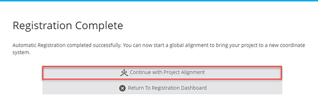
After the project has been registered, you will be promoted to change global coordinates. Click on “Continue with Project Alignment” to create a new project alignment.

ProjAlignment_RegComplete.jpg

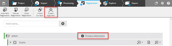
Alternatively, you can access the Project Alignment Tools from the Registration Tab as shown below:
ProjAlignment_RegTab.jpg


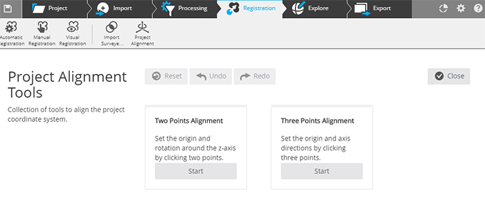
You may then create a new global coordinate based on either a two point or three point alignment.

ProjAlignment_2and3Point.jpg

ProjAlignment_2PointSelect.jpgTwo Point Alignment

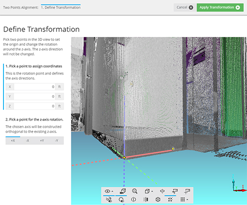
Use the two-point alignment tool to change the origin position or the orientation of your project's coordinate system while preserving the level. You can select an existing scan point to serve as the origin, or establish the desired coordinates for the selected point. You need to type the coordinates in the text boxes.
To use the two-point alignment tool:

  1. Select a point that should serve as the new origin.
  2. If the desired coordinates for the selected point are different than 0,0,0, please enter the X, Y and Z values for the point. Once the transformation is applied, those values will be the coordinates of the selected point.
  3. Select another point. This point defines the direction of the an axis- The second axis will be perpendicular to the first axis.

Walkthrough Video

Cannot view the video? Click here to download this video.

ProjAlignment_3PointSelect.jpg
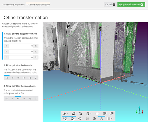
Three Point Alignment

Use the three point alignment tool to change the origin position and/or the orientation of your project's coordinate system. You can select an existing scan point to serve as the origin, or establish the desired coordinates for the selected point. You need to type the coordinates in the text boxes. To use the three point alignment tool:

  1. Select a point that should serve as the new origin, or a point that is close to where the new origin will be.
  2. If the desired coordinates for the selected point are different than 0,0,0, please enter the X, Y and Z values for the point. Once the transformation is applied, those values will be the coordinates of the selected point.
  3. Select a point to define direction of the the first axis.
  4. Select another point. This point defines the direction of the second axis.
  5. The three points selected will form a plane / level of this project. Only use the 3 point alignment if you will not be using the inclinometer for the project.