As-Built As-Built - Revit As-Built - AutoCAD VirtuSurv - VirtuSurv 2018 As-Built - Modeler VirtuSurv - VirtuSurv 2019          
BuildIT BuildIT - Projector BuildIT - Construction BuildIT - Metrology              
CAM2 CAM2 - SmartInspect CAM2 - 2024 CAM2 - 2023 CAM2 - 2018 CAM2 - Measure 10 CAM2 - Measure Q CAM2 - Measure X CAM2 - Measure 3/4 CAM2 - AnthroCAM CAM2 - 2019
CAM2 CAM2 - 2020 CAM2 - 2021                
Cobalt 3D Imager 3D Imager - Cobalt                  
Cobalt Design Cobalt Design - M Cobalt Design - S Cobalt Design - Dual              
Computers Computers - All Computers                  
FARO Aras 360 & CAD Zone FARO CAD Zone - Fire & Insurance FARO CAD Zone - Crime & Crash FARO CAD Zone - CZ Point Cloud FARO CAD Zone - First Look Pro FARO 360 - Reality FARO 360 - HD FARO 360 - Blitz FARO 360 - Genius    
FARO Connect FARO Connect - Connect                  
FARO Zone present4D - present4D                  
FARO Zone 2D FARO Zone 2D - 2018 FARO Zone 2D - 2019 FARO Zone 2D - 2020 FARO Zone 2D - 2021 FARO Zone 2D - 2022 FARO Zone 2D - 2023 FARO Zone 2D - 2024      
FARO Zone 3D FARO Zone 3D - 2018 FARO Zone 3D - 2019 FARO Zone 3D - 2020 FARO Zone 3D - 2021 FARO Zone 3D - 2022 FARO Zone 3D - 2023 FARO Zone 3D - 2024      
FARO Zone 3D Advanced FARO Zone 3D Advanced - 2018 FARO Zone 3D Advanced - 2019 FARO Zone 3D Advanced - 2020 FARO Zone 3D Advanced - 2021 FARO Zone 3D Advanced - 2022          
FaroArm/ScanArm FaroArm/ScanArm - Quantum S FaroArm/ScanArm - Quantum M FaroArm/ScanArm - Quantum E FaroArm/ScanArm - Edge FaroArm/ScanArm - Fusion FaroArm/ScanArm - Prime FaroArm/ScanArm - Platinum FaroArm/ScanArm - Legacy Quantum FaroArm/ScanArm - Titanium FaroArm/ScanArm - Advantage
FaroArm/ScanArm FaroArm/ScanArm - Digital Template FaroArm/ScanArm - Gage FaroArm/ScanArm - Quantum S Max FaroArm/ScanArm - Quantum M Max FaroArm/ScanArm - Quantum E Max FaroArm/ScanArm - Gage Max FaroArm/ScanArm - Quantum X.S FaroArm/ScanArm - Quantum X.M FaroArm/ScanArm - Quantum X.E  
GeoSLAM Software GeoSLAM Software - Connect GeoSLAM Software - Draw GeoSLAM Software - Hub GeoSLAM Software - Volumes            
GeoSLAM ZEB GeoSLAM ZEB - Horizon GeoSLAM ZEB - Horizon RT GeoSLAM ZEB - Revo GeoSLAM ZEB - Revo RT GeoSLAM ZEB - Go          
Hand Held Scanner 2D Hand Held Scanner - ScanPlan 3D Hand Held Scanner - Freestyle3D 3D Hand Held Scanner - Freestyle3D X 3D Hand Held Scanner - Freestyle3D Objects 3D Hand Held Scanner - Freestyle 2          
Language Quality HT MT AT NT INT - Internal Sales - Internal Resources Sales - Order and Quote Sales - Product Info Sales - Sales Readiness Sales - Training
Language Quality Sales - Product Launch Sales - Promotions CS - Quote to Invoice CS - Phone System CS - New Hire Training CS - General CS - Product Info CS - Licensing CS - Onboarding CS - Procedures General
Language Quality CS - Procedures Salesforce CS - Procedures Loaner CS - Procedures SAP              
Languages Language - English Language - Japanese Language - German Language - Chinese Language - Spanish Language - Italian Language - Portuguese Language - French Language - Korean  
Laser Projector RayTracer - RayTracer Laser Projector - Tracer M Laser Projector - Tracer SI              
Laser Radar Imaging Laser Radar - VectorRI                  
Laser Scanner 3D Laser Scanner - Focus S 3D Laser Scanner - Focus M 3D Laser Scanner - Focus3D 3D Laser Scanner - Focus3D X 3D Laser Scanner - Focus3D X HDR 3D Laser Scanner - Focus3D S 3D Laser Scanner - Photon 3D Laser Scanner - Focus S Plus 3D Laser Scanner - Swift 3D Laser Scanner - Focus Premium
Laser Scanner 3D Laser Scanner - Focus Core 3D Laser Scanner - Focus Premium Max                
Laser Tracker Laser Tracker - Vantage Laser Tracker - ION Laser Tracker - Vantage S Laser Tracker - Si Laser Tracker - X Laser Tracker - Xi Laser Tracker - Vantage E Laser Tracker - Vantage S6 Laser Tracker - Vantage E6  
Legacy Gage Legacy Gage - Bluetooth Legacy Gage - Plus Legacy Gage - Standard Legacy Gage - Power            
Legacy Software Legacy Software - CAM2 Gage Legacy Software - Gage Software Legacy Software - Insight              
Mobile Scanner Mobile Scanner - Orbis                  
PointSense PointSense - Basic PointSense - Pro PointSense - Building PointSense - Plant PointSense - Heritage PointSense - Revit CAD Plugin - TachyCAD Building CAD Plugin - TachyCAD Archeology CAD Plugin - TachyCAD Interior CAD Plugin - PhoToPlan Basic
PointSense CAD Plugin - PhoToPlan CAD Plugin - PhoToPlan Pro CAD Plugin - PhoToPlan Ultimate CAD Plugin - DisToPlan CAD Plugin - MonuMap CAD Plugin - hylasFM CAD Plugin - VirtuSurv      
RevEng RevEng - RevEng                  
ScanArm ScanArm - Design ScanArm 2.0 ScanArm - Design ScanArm ScanArm - Forensic ScanArm ScanArm - Design ScanArm 2.5C            
SCENE SCENE - Capture and Process SCENE - WebShare Server and 2Go SCENE - WebShare 2Go App SCENE - 2024 SCENE - 2018 SCENE - 7.x SCENE - 6.x SCENE - 5.x SCENE - 4.x SCENE - LT
SCENE SCENE - 2019 SCENE - 2go App SCENE - 2020 SCENE - 2021 SCENE - 2022 SCENE - 2023        
Serial FaroArm Serial FaroArm - Silver Serial FaroArm - Gold Serial FaroArm - Bronze              
Sphere FARO Sphere - Sphere                  
Visual Inspect Visual Inspect - App Visual Inspect - CAD Translator                
WebShare WebShare - Enterprise WebShare - WebShare Cloud                

FARO Sphere

Sphere

FARO® Knowledge Base

Using RAD Reference Height Markers in FARO Flatness Check
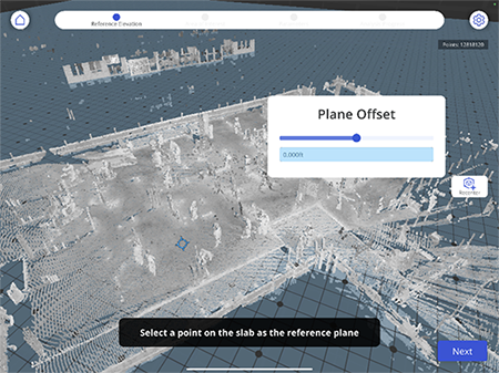
FlatRADMarker-PlaneOffset.pngOverview

Flatness Check allows you to quickly analyze the concrete deck for height deviations and unevenness. To do so, you pick a point on the slab as the analysis reference plane. It is also possible to select a benchmark point and define the analysis plane offset.

Often identifying one of these points can be cumbersome, as it may require zooming in and out and moving around in the point cloud to identify the correct point.


Solution

Quite often on construction sites a benchmark reference already exists for each level. This is typically laid out by a surveyor and marked on an existing elevator shaft wall or column. Below is an example of a benchmark on a German construction site (1m above finished floor):

FlatRADMarker-BenchmarkExample.png

FARO Flatness Check version 11.0 introduced the ability to automatically detect specific RAD (Ringed Automatically Detected) markers. Follow the steps below to ensure the Flatness Check app analyzes your concrete deck correctly against the reference height.

  1. On your computer, download and open the "Large RAD Markers" PDF file. Please review the printing and usage guidelines on page one of the PDF file.
  2. Print one or more targets from the file, e.g. target number 1401 (page two of the PDF). Depending on the concrete deck size and elements on the floor you may need one or more targets. We recommend one target per 2.000sqft (~ 200m²).
    • Currently the Focus Scanner scans with 1/8 resolution. Therefore the marker printed on US letter (~A4) paper size needs to be within 9ft 10in distance (3m) to ensure automated detection. If you plan to place the targets on a wall further away, we suggest to increase the paper size to Tabloid, A3 or even larger.
    • Note: Check for printing individual page(s) only, as the file comes with more than 200 pages!
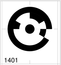
      FlatRADMarker-RAD1401.png
  3. On the site, place the printed target(s) at the benchmarked reference height and ensure the scanner has free line of sight to the target. Use the horizontal lines at the edges of the target to ensure the center is at the correct level. It is recommended to place the RAD marker in the direction of the deck and as close as possible to the deck to minimize the angular error. If the scanner view is obstructed, transfer the reference height to other site elements (using a Total Station, water/laser level, or other technique) and place more targets as needed.
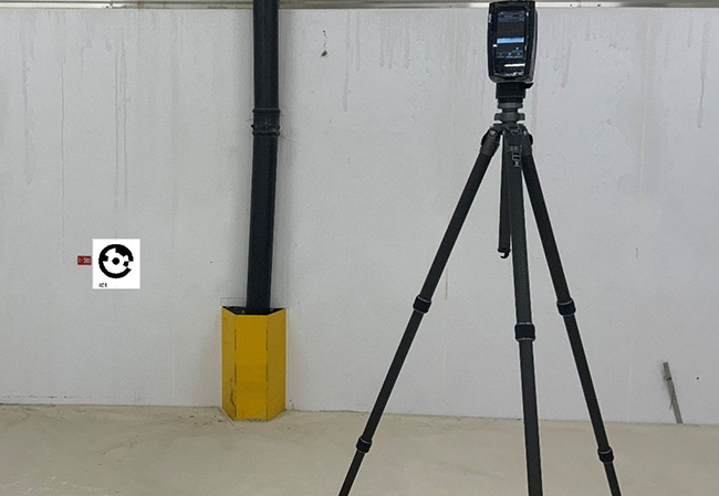
    FlatRADMarker-TargetPlacement.png
  4. Start the scan.
  5. During the analysis process, the app will detect the RAD Marker and pick it as the reference point. You’ll need to specify the plane offset accordingly.
    • Note: To move the analysis plane down, you’ll need to specify the height with a negative value “-“.
  6. Continue the analysis and identify critical areas where your deck might be below or above the height specified in the design documents.