Mounting Options for the FaroArm
Overview
This article contains information on the different types of mounts available for the FaroArm, including:
- Mounting requirements and how to mount the FaroArm (per generation)
- Mount types, including part numbers
- Drawing dimensions, including high-definition PDFs available for download
- Troubleshooting information
FARO offers a selection of tripods, rolling stands, and granite surface work carts. See the following articles for more information:
Mounting Requirements
The FaroArm is portable and can be mounted in a variety of environments. The counterbalance provided by the tension spring generates torque at the base of the FaroArm, allowing ease of mobility. To achieve optimum machine accuracy, the mounting must meet certain requirements. See the next section for instructions.
Note: Do not mount the FaroArm sideways, on a wall, or upside down (inverted), unless it is specifically designed to do so (known as Inverted Arms). This will affect accuracy and add stress to the FaroArm. Therefore, the FaroArm must me mounted in an upright position.
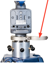
Mounting the FaroArm (Quantum and Edge)
- Place the Quantum onto the 3½” ring of your tripod or surface mount plate. Thread the collar onto the ring and hand tighten.
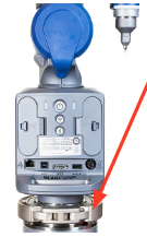
- Tighten the collar using the attached handles.
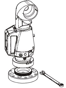
Mounting the FaroArm (Pre-Edge)
- Attach the 3.5" (3½) threaded ring and surface mount plate to any stable location. Tighten all mounting bolts to 100-inch pounds.
- Place the FaroArm on top of the 3.5” (3½) threaded ring.
- Screw the threaded collar clamp onto the base of the FaroArm and the 3.5” (3½) threaded ring.
- Use a wrench, if needed, to tighten the threaded collar clamp.
Types of Mounts
3½ Mounting Ring
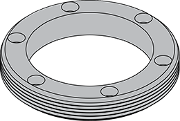
The 3½” Mounting Ring is typically used for all FaroArm models. The ring has six holes, allowing it to be mounted to any flat surface. The outside of the ring is threaded to accept the locking collar of the FaroArm.
Recommended Mounting Fasteners: 1/4-20 x 1” (SHCS) Socket Head Cap Screw, Stainless Steel
The above fastener is available from FARO, p/n 10429
We offer the following two types:
- Part #: IG-27 (Supersedes Part Numbers: 1149, 10066)
Material: Carbon Steel per ANSI 1040 or ANSI 1045 or Equivalent
Finish: Nickplate per QQEL -N-290, Class I. Grade G Min., Bright Finish.
- Part #: 21203 (Stainless Steel, For High Corrosion Environments)
Material: 316 Stainless Steel
Finish: Passivation Per ASTM A967
Dimensional Drawing for 3½ Mounting Ring

Click here to download a high-resolution PDF.
Square Base Plate and 3½ Mounting Ring Kit
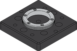
This kit includes both the square base plate and the 3 ½ mounting ring. The ring is pre-mounted using 10-32 x 3/4" socket head cap screws.
Recommended Mounting Fasteners: 1/4-20 x 1” (SHCS) Socket Head Cap Screw, Stainless Steel
The above fastener is available from FARO, p/n 10429
Attention: Quantum S/M/E FaroArm users:
Do not use a fastener through the center hole of the mounting plate. The head of the fastener will interfere with the bottom of the FaroArm.
Part #: 14178
Dimensional Drawing for Square Base Plate and 3½ Mounting Ring Kit

Click here to download a high-resolution PDF.
Circle Base Plate and 3½ Mounting Ring Kit (Discontinued)
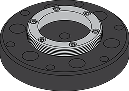
(Alternative name: Surface Mount Plate)
Recommended Mounting Fasteners: 1/4-20 x 1” (SHCS) Socket Head Cap Screw, Stainless Steel
The above fastener is available from FARO, p/n 10429
Dimensional Drawing for Circle Base Plate and 3½ Mounting Ring Kit

Click here to download a high-resolution PDF.
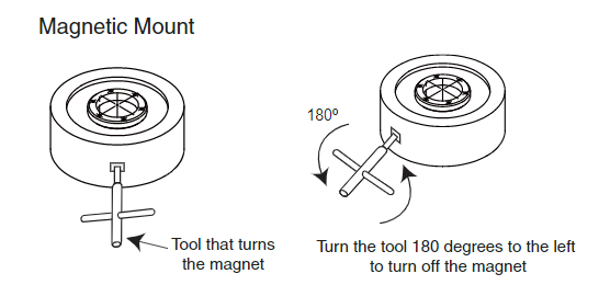
Magnetic Mount
![]()
Part #: 11516
Click here to download the product specifications.
The Magnetic Mount is used for all FaroArm modes. It is a large, magnetic base used to mount the FaroArm to surface plates, tools, and other iron-containing metal surfaces. It comes with the 3½” ring on top and the tool to turn the magnet on and off.
|
To use the Magnetic Mount
|
 |
Dimensional Drawing for Magnetic Mount

Click here to download high-resolution PDF.
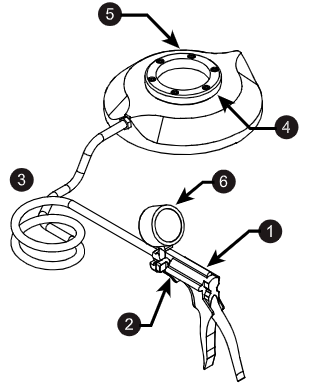
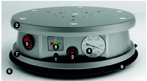
Vacuum Mount
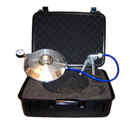
Part #: 13402-002, Metric
Dimensions: Diameter= 10.75" (273mm), Height=1.75" (44.4mm).
Part #: 13403-002 (Metric) is available for the 4ft. model FaroArm and the FARO Gage.
Dimensions: Diameter=7.5" (190mm), Height=1.4" (35.5mm)
The Vacuum Mount is meant for every size and model of USB FaroArm and Faro Laser Tracker. Its purpose is to quickly, easily and rigidly mount the FaroArm and Tracker to granite surfaces without degradation in the accuracy of the readings.
|
To use the Vacuum Mount Note: A bottle of Vacuum Oil for the vacuum mount is included in the kit. Use the oil to create the vacuum seal between the mount and the granite surface. The reorder part number is XH26-0030.
When you finish measuring, loosen the knob [2] to open the Pressure Relief Valve and release the vacuum. |
|
|
Best Practices
|
|
Battery-Operated Vacuum Mount
Part #: 15320
The Battery-Operated Vacuum Mount secures the FaroArm to granite and other air-impermeable surfaces. A battery-powered mini vacuum pump creates a vacuum between the FaroArm base and the surface to secure the Vacuum Mount via suction. Adapters secure the FaroArm to the mount’s upper plate.
|
To use the Vacuum Mount
|
|
|
Best Practices CAUTION: Improper operation may result in injury!
|
|
Troubleshooting
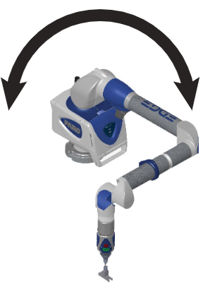
Verifying Position and Stability (Quantum and Edge)
- Start the FaroArm Manager software and connect your FaroArm.
- Click Diagnostics > Base Deflection.
- Set up the FARO compensation cone, or a hole on your part, approximately ⅔ of the FaroArm's reach away from its base.
- Place a properly compensated probe firmly in the cone. The probe must be well-seated in the hole.
- Press the green Front button and move the tubes and joints of the FaroArm while keeping the probe firmly seated in the cone.
- Press the green Front button to reset the screen at any time.
- Press the red Back button to stop.
- Any deflection of the base is recorded and displayed on the screen. All of the points must be within the circle on the graph.
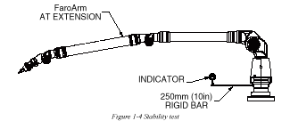
Verifying Position and Stability (Pre-Edge)
To verify the position and stability of a FaroArm, mount a dial indicator on the FaroArm as high as possible, but low enough so that the counterbalance or decelerator does not contact the indicator as the FaroArm moves around encoder 1 or the encoder at the base.
- Mount the FaroArm on the surface.
- Torque down the locking ring or all the hex bolts with the Allen key.
- Tighten down the probe with a wrench over finger tight.
- With the FaroArm in a resting position, mount the dial indicator so that it rests against the base.
- Reset the dial indicator so that it reads zero.
- Pull the FaroArm from rest and move it around its volume while reading the dial indicator.
- Move the indicator to a new location (i.e. 45 or 90 degrees).
- Repeat.
The dial indicator should show no movement while the FaroArm is being moved around its volume.
| FaroArm Size | Error at 250 mm (10 in) from center of base |
Total Angular Deflection |
|---|---|---|
| 4 ft. |
<<: 0.005 mm |
<<: .529 µm/mm |
| 6 ft. | <<: 0.005 mm <<: 0.0002 inches |
<<: 564 µm/mm |
| 8 ft. | <<: 0.005 mm <<: 0.0002 inches |
<<: .529 µm/mm <<: 20.83 micro inches/inch |
| 10 ft. |
<<: 0.007 mm |
<<: .719 µm/mm |
| 12 ft. | <<: 0.008 mm <<: 0.0003 inches |
<<: .847 µm/mm |
Note: The bar must have a 6M thread on one end to connect to the FaroArm. Measure the deflection of the bar when the FaroArm is fully extended. The angular deflection and lateral deflection of the base must not exceed the values in the table above.