Tank Deformation Analysis with BuildIT Construction

Objective
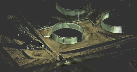
Use BuildIT Construction to Import an E57 file and perform tank deformation analysis on a storage tank to determine how vertical and round the tank is.

You’ll learn:
- A simple workflow from importing the files to producing a report of the deformation analysis.
- Opening BuildIT, import a *E57 Cloud file.
- Performing the Tank Deformation Commands
General Procedure:
- Import E57 file
- Prepare the Data for Analysis
- Tank Deformation Analysis Commands
Import E57 File
- Import scans by using the following method:
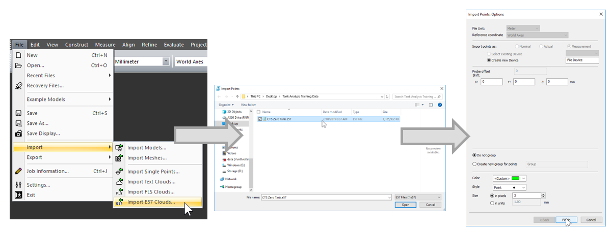
- In the menu bar, select "File > Import > Import E57 Clouds"

- In the menu bar, select "File > Import > Import E57 Clouds"
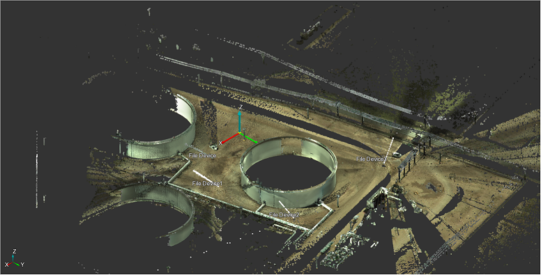
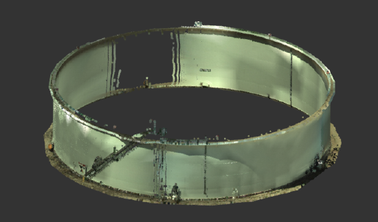
Select the file "CTS Zero Tank.e57" from the training data and open.
Prepare the Data for Analysis
- Combine the scans into one.
- Select "Refine > Merge Clouds"
- For "Clouds", select the imported scans.
- For "Name", enter "Combined"
- Select "Apply"

- Section out of tank itself.
- Select "Refine > Split Clouds"
- Select the "Combined" cloud.
- Use the polygon selection tool to section out of the tank itself.
- Use the Inside/above to keep only the points within the polygon.
- Select "Apply"

- Separate the tank shell from the foundation.
- Using the same command above, separate the tank foundation from the shell, keeping both the shell and foundation point clouds.

- Using the same command above, separate the tank foundation from the shell, keeping both the shell and foundation point clouds.
Tank Deformation Analysis Commands
- Create Tank Definition
- Create Tank Definition
- Select “Evaluate > Tank Analysis > Tank Definition From Scan”
- Enter a name for the Tank. This will also appear on the report.
- Select the tank shell cloud from step 2.
- Select the foundation cloud from step 2.
- Select an unwrapping/Clocking point. This is typically the entry point to the tank, or the first defined station.
- Ensure “Use inclinometer as reference” is checked.
- When this is checked, the Z axis of the cylinder is locked to the scanner’s inclinometer orientation.
- When this is unchecked, the foundation plane is used as the upright reference.
- Select “Apply”

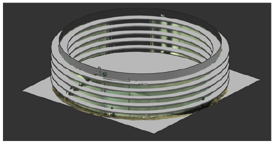
- Define Horizontal Stations
- The first step is to define horizontal stations. Tanks are analyzed for roundness, which measures if the tank is bulging or contracting. This is typically defined a certain distance above or below the weld seams. This step defines these for later analysis. There are two methods within the tank analysis commands.
- Offset from Weld Seams: choose two weld seams and the software will use this offset to define the rest automatically. This is what we will use in this example.
- User-Specified Points: For tanks that are not similar distances between weld seams, users can create points with “Construct > Point > Point” and use these for defining the horizontal stations.
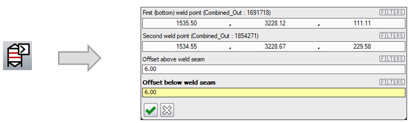
- Select “Evaluate > Tank Analysis > Define Horizontal Stations – Offset from Weld Seams”
- Select the first and second weld seams.
- Enter the offset below and above the weld seam, here 6” will be used.
- The first step is to define horizontal stations. Tanks are analyzed for roundness, which measures if the tank is bulging or contracting. This is typically defined a certain distance above or below the weld seams. This step defines these for later analysis. There are two methods within the tank analysis commands.
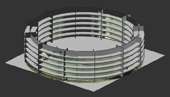
- Define Vertical Stations
- The next step is to define vertical stations, which are used to measure if the tank is tilting at several points.
- Select "Evaluate > Tank Analysis > Define Vertical Stations"
- Enter the number of vertical stations.
- Select whether to use clockwise or counter-clockwise naming convention
- Select "Apply"

- Perform the Deformation Analysis
- Within this step, several items happen:
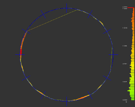
- Horizontal Analysis
- The stations defined earlier will be compared to the design or ideal cylinder. The command will give the actual numbers of deviation, as well as a visualization of the results.
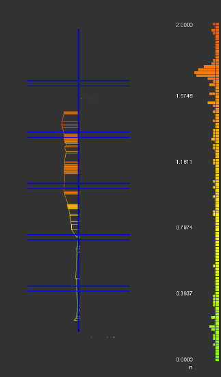
- Vertical Analysis
- The stations defined earlier will be compared to the design or ideal cylinder. The command will show how upright the scan data sits versus design, which actual deviations and a visualization.
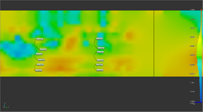
- Unwrapped Grid Analysis
- The tank will then be unwrapped and deviation shown as a flat surface. This can help visualize where deviation exists on the tank itself. Users can also compare the scan data to the design cylinder by using Surface Deviation Analysis. The grid will also be annotated at areas where the horizontal and vertical station intersect.
- Horizontal Analysis
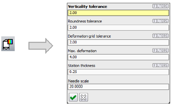
- Select "Evaluate > Tank Analysis > Deformation Analysis"
- Enter a "Verticality Tolerance"
- Verticality is a measure of how upright the tank sits. Areas that are larger than this tolerance will be visualized as red, or out of tolerance.
- Enter a "Roundness Tolerance"
- Roundness is a measure of how buckled or bulging a circle is compared to an ideal circle. Areas that are larger than tolerance will be visualized as red, or out of tolerance.
- Enter a "Deformation Grid Tolerance"
- Where the vertical and horizontal stations intersect, a scan point will be compared to the ideal cylinder. This tolerance represents what's considered out of line for that grid.
- Enter a value for "Max Deformation"
- This value controls how far the analysis will search in or out of the shell to find points. So if the value is set to 4 inches, it will only search 4 inches in or out of the design cylinder.
- Enter a "Station Thickness"
- This value controls of how much data is used in each station. The default value of 0.25 inch means that we look up or down and left or right 0.25 inches to define and analyze. Larger values include more points in the analysis.
- Enter a "Needle Scale"
- This value controls how the deviation is represented visually. If the deviation is 1 inch and the needle scale is 10, the deviation is represented visually as 10 inches. For more exaggerated analysis, increase this value.
- Select "Apply"
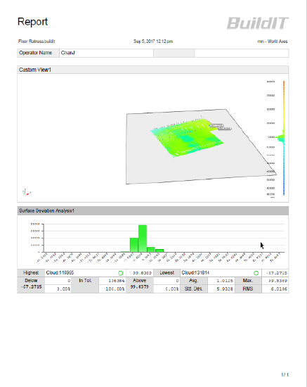
- Within this step, several items happen:
- Once the command is completed, navigate to the report tab and run the report.

Recap:
- Congratulations, you have completed the tank deformation analysis module! By now, you should have a grasp of the following:
- Open BuildIT
- Import *E57 file to BuildIT Construction
- Prepare the Data Analysis
- Use the Tank Deformation Analysis Commands
- Export a report