Creating a GD&T Position Call-Out and True Position Calculation in CAM2
Overview
How to apply a GD&T True Position call-out to a feature.
Download a PDF of this procedure:
Preparation
- Create the datum features as detailed in the following articles:
- An alignment or coordinate system is required
- Measure the features that require the GDT call-out.
- All measured features must have nominal values associated or manually entered.
- All measured features of size must have correct tolerance values for size entered.
- All datum features must have nominal values associated or manually entered.
Creating the GDT Call-out
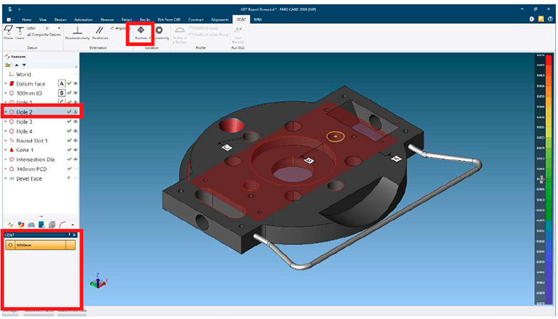
- Select the GDT tab
- Highlight the required feature in the Feature panel
- From the ribbon select
 Position
The GDT panel will open in the lower LH corner of the UI
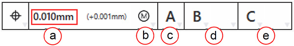
- Within the GDT panel:
- Click on the tolerance value to edit
- If required select feature material modifier
- Select primary datum
- Select datum material modifier if available (dependent upon datum type)
- Once the primary datum is selected, a second cell will appear
- Selecting Active Alignment does not allow additional selections
- Select secondary datum
- Select datum material modifier if available (dependent upon datum type)
- Once the secondary datum is selected, a third cell will appear
- Select tertiary datum
- Select datum material modifier if available (dependent upon datum type)
Note: A ‘greyed-out’ GDT icon indicates that the selected feature does not support this call-out.
The call-out will be calculated and the result will be shown in the GDT label displayed in the 3D viewer.
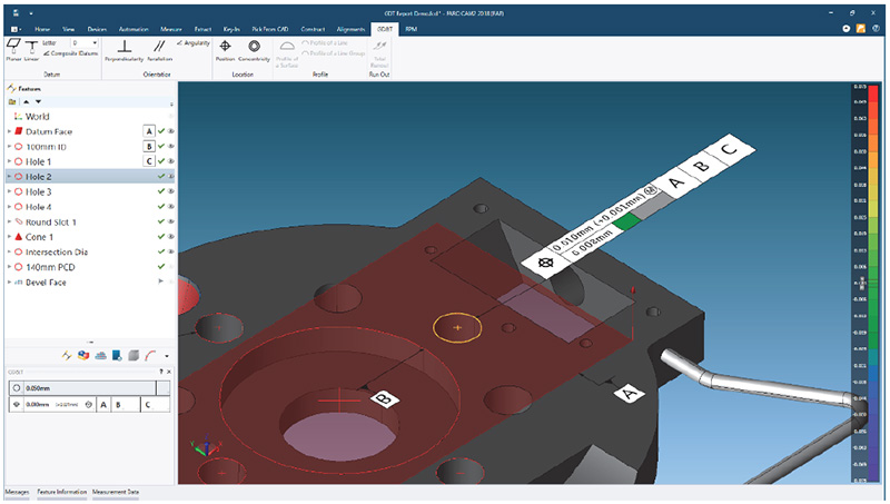
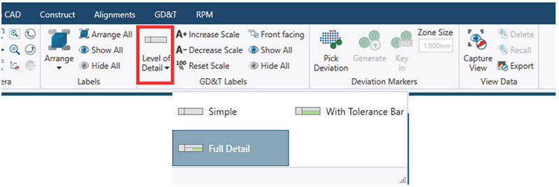
Note: To display results in the GDT label select via View > GDT Label > Level of Detail
Copying GDT Call-outs to Other features
This allows multiple features of the same type to have the same call-out applied
- Apply the call-out to the first feature
- Highlight the first feature
- Right click and select Copy Tolerances
- Multi-select other features
- Right click and select Paste Tolerances
- Message ‘Do you also want to paste the GDT tolerances?’, select Yes
The GDT call-out will be applied to the selected features, and the GDT label will be displayed.
How True Position is Calculated
True Position Calculation of Circles and Torus
This is a special case to deal with Circles where the center point is compared to the axis of the Nominal circle. This value can be interpreted as Coaxiality as defined in ISO 1101. The True Position is computed as twice the distance of the center point of the Measured feature to the nominal axis, as an infinite line.
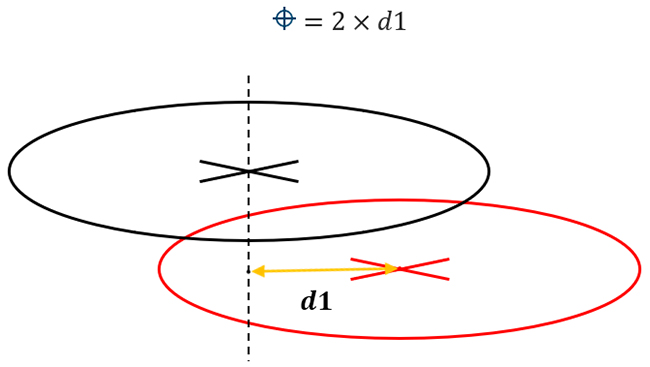
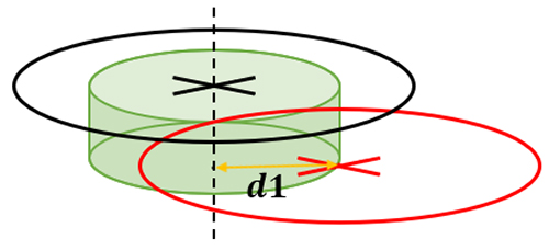
The True Position value represents the diameter of a cylinder, displayed in green below, around the nominal axis which contains the center point from the measured feature.
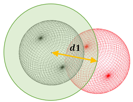
True Position Calculation of Points and Spheres
The true position is calculated as twice the 3D distance between the measured and the nominal point. This True Position value represents a sphere around the Nominal Point which contains the Actual Point.
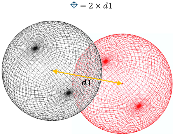
The True Position value represents the diameter of a sphere, displayed in green below, around the nominal Point which would contain the Actual Point.
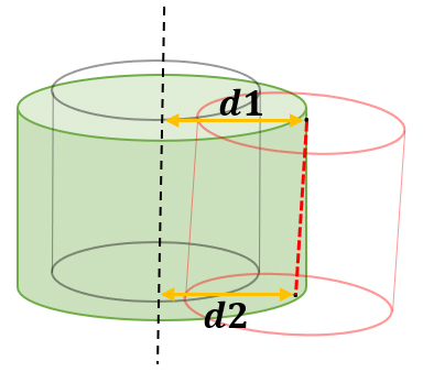
True Position Calculation of Lines, Cylinders, and Cones
When calculating the True Position of a Line-reduced feature, the end-points of the Measured feature axis are compared to the Nominal axis, as an infinite line. The end-points of the measured feature are determined by the captured measurement points. The True Position value is twice the largest distance from the endpoints to the nominal axis line.
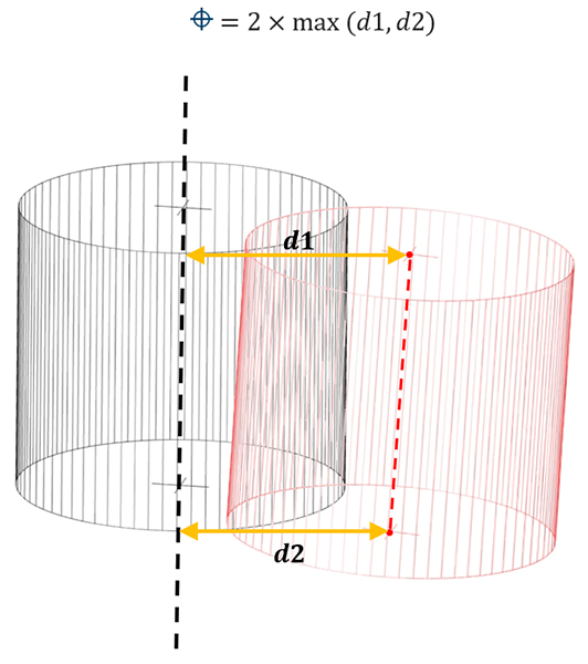
The True Position value represents the diameter of a cylinder, displayed in green below, around the nominal axis which contains the full axis line from the measured feature.
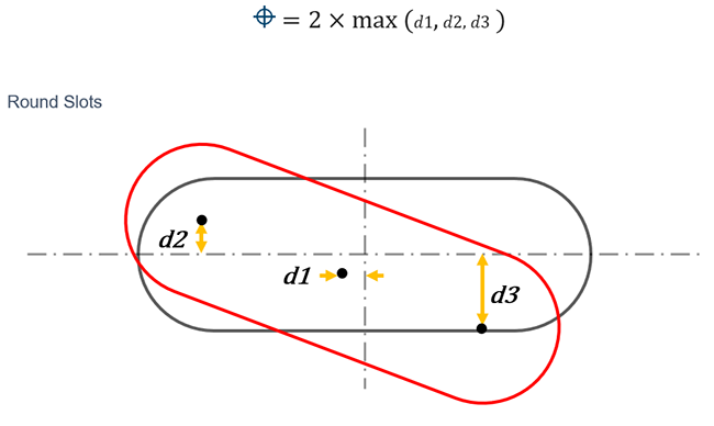
True Position Calculation of Round Slots
When calculating the True Position of round slot features, the center and calculated arc centers and center point of the measured feature are used. The arc center points are compared to the nominal axis running the length of the slot to control rotation, and the center point is compared to an axis at the nominal slot center, perpendicular to the slot axis (length) to calculate translation.
Three dimensions are calculated, d1, d2 and d3 which are used to establish the positional deviation of the feature.
The True Position value is twice the maximum value of d1, d2 and d3 calculations.
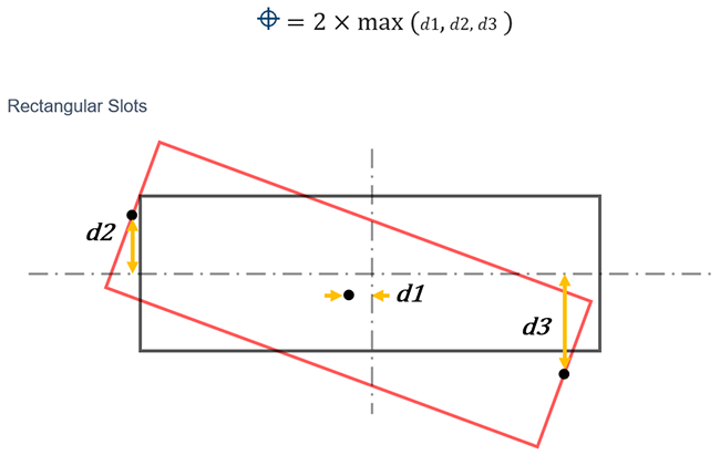
True Position Calculation of Rectangular Slots
When calculating the True Position of rectangular slot features, the center and calculated end points of the measured feature are used. The end points are compared to the nominal axis running the length of the slot, to calculate rotation deviation, and the center point is compared to an axis at the nominal slot center perpendicular to the slot axis (length) to calculate translation deviation.
Three dimensions are calculated, d1, d2 and d3 which are used to establish the positional deviation of the feature.
The True Position value is twice the maximum value of d1, d2 and d3 calculations.
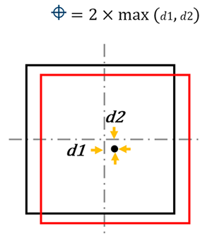
True Position Calculation of Square Slots
When calculating the True Position of square slot features, the center point deviation is used.
Two dimensions are calculated, d1 and d2 are combined to establish the 2D deviation of the center point.
The True Position value is twice the maximum value of the 2 calculations
See Also
Keywords:
GD&T, Help Sheet, GDT007