Measuring a Gauge Block or Gauge Ring Using the FaroArm and CAM2
Overview
Measuring a gauge ring or block can be done with a FaroArm and CAM2 software. The accuracy of the results will depend greatly on the type of CAM2 features you are using and how they are used.
FaroArm Setup and Accuracy
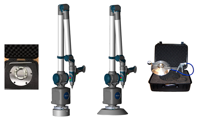
To ensure the FaroArm setup is the most accurate the mounting of the FaroArm must be stable, therefore we recommend using the magnetic or vacuum mounts.
- Magnetic Mount - The mounting surface and the bottom surface of the Magnetic Mount must be clean, perfectly flat, and free of burrs. Check both surfaces. If they are not flat, imperfections can be removed by lightly stoning with a hand-held grinding stone. The full area of the Magnetic Mount must be in contact with the mounting surface for maximum stability.
- Vacuum Mount - Ensure the granite is flat, clean, and undamaged. Use lubricant to moisten seal.
For more information on mounting options, see Mounting Options for the FaroArm.
FaroArm Accuracy:
Quantum series FaroArm accuracy testing and certification is according to the ISO 10360-12 standard. The ISO 10360-12 standard specifies four accuracy tests The tests results are an error, and each test has a Maximum Permissible Error (MPE).
| Test | Test Description |
|---|---|
 |
PForm-Sphere Probing Form Error. The operator measures a sphere with the Quantum Max probe. The error is maximum distance of any point from the best-fit sphere |
 |
PSize-Sphere Probing Size Error. The operator measures a sphere with the Quantum Max probe. The error is the difference between the measure and actual diameter of the sphere. |
 |
LDia-Sphere Location Diameter Error. The operator measures a sphere with the Quantum Max probe from multiple orientations. The error is the diameter of the spherical zone containing the centers of the measured spheres. |
 |
EUni-Unilateral Distance Error. The operator measures two spheres, or two points, with the Quantum Max probe. The error is the difference between the measure and actual length between the spheres or points. |
SPAT Test:
The SPAT test is used to check the repeatability of the FaroArm X, Y, and Z coordinates throughout its full range of motion. For a demonstration, see Mount Stability and Single Point Articulation Test (SPAT) with the FaroArm
Measuring a Gauge Ring (PSize)
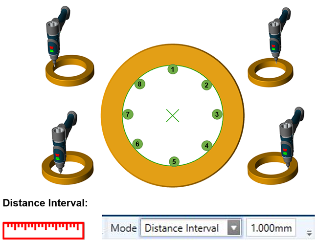
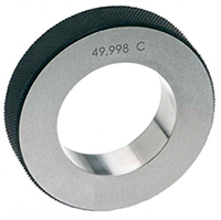 We recommend measuring the diameter of gauge ring as "Circle" feature and use the top plane of the gauge ring as your reference "Plane" feature. For the diameter, we recommend measuring 8 points that are evenly spaced.
Tips:
- Do not flip the FaroArm over its base during measuring the circle feature.
- Using a distance interval can help you ensure the readings are evenly spaced.
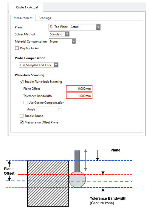
Plane-Lock Scanning
Plane-lock Scanning enables you to specify a depth value for a plane projection feature. As you measure the feature, CAM2 will automatically record a measurement whenever the probe traverses a plane offset a given depth value below the projection plane. Plane-lock Scanning is especially helpful when measuring thin sheet metal planar features.
|
Plane-lock Scanning enables you to specify a depth value for a plane projection feature. As you measure the feature, CAM2 will automatically record a measurement whenever the probe traverses a plane offset a given depth value below the projection plane. Plane-lock Scanning is especially helpful when measuring thin sheet metal planar features. Plane-lock Scanning options are as follows:
|
 |
Why not use a Cylinder feature?
The cylinder feature is a 3D feature and is mostly use to analyze the position of a cylinder perpendicularity or concentricity. A cylinder requires a minimum of 6 readings to be able create the feature and the diameter is calculate on “Best Fit”.
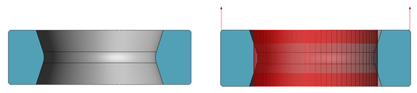
| Perfect perpendicular and cylindrical cylinder: | 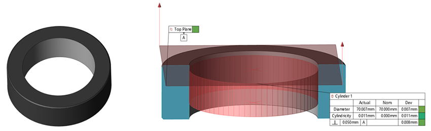 |
| Cylinder Not perpendicular: (result: Diameter can be ok, but the center can be out of position) |
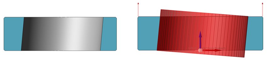 |
| Cylinder is more a cone shape: (result: Diameter will average “best fit” and cylindricity will be out of tolerance) |
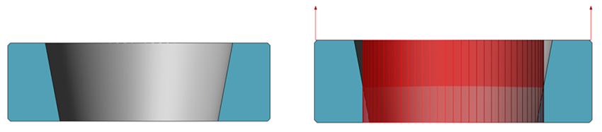 |
| Cylinder is not cylindrical: (result: Diameter will average “best fit” and cylindricity will be out of tolerance) |
 |
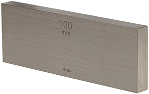
Measuring a Gauge Block (EUni)
 Many users are measuring Planes and checking the length between these planes to determine if the gauge block is correct. But is this the best method?
Understanding the Plane feature:
The Plane feature is a best fit feature that uses the readings to create a plane.
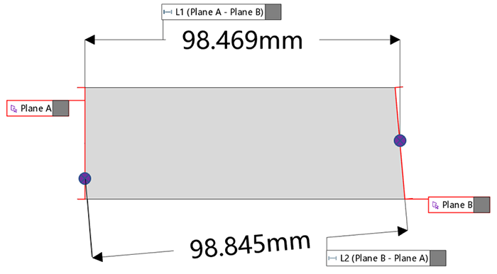
When measuring a length between two planes, CAM2 will your first selected plane and create a length perpendicular along the vector direction of the first plane. The length will only be created if the two planes are within 3° parallel of each other.
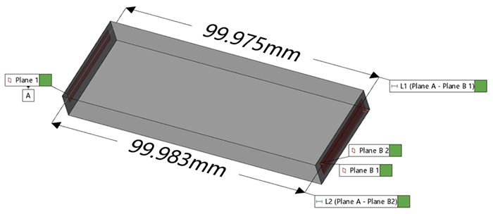
Perfect Parallel Planes:
Non Parallel Planes:
Best Practice to Measure a Gauge Block
We recommend measuring the distance of the gauge block using a Plane as one side and the other side as surface points.
- First measure one side of the gauge block as a Plane with a minumn of 5 points. The flatness of this surface should be under 0.030 mm (.001") to have a good reference Plane.
- In CAM2 you can use this measured Plane as the reference surface and measure the other side of the gauge block with Inspect Surface Points. The vector direction of the Plane sets the compensation direction of the Inspect Surface Point.
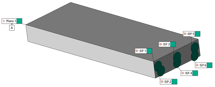
- After you measured these Inspect Surface Points (ISPs), you can construct lengths between each Inspect Surface Point and the Plane feature.
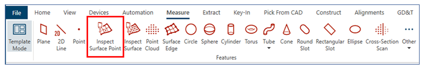
How To Use Inspect Surface Points if You Don’t Have CAD
Tis example is using CAM2 2023.1.
- Measure the reference Plane one side of the gauge block. (Plane A)
- Construct Plane By Offset.
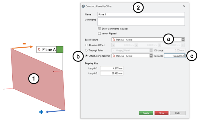
- Base Feature – Plane A – Actual.
- Offset Along Normal – Plane A – Actual.
- Distance – Enter the distance of the gauge block. (+ ve or – ve)
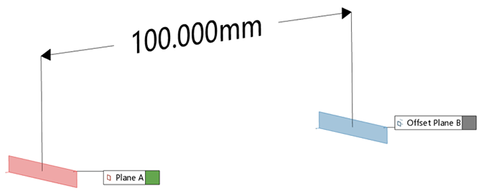
- Select the Offset Plane B in the Features panel.
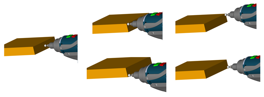
- Click on Inspect Surface Point and measure.
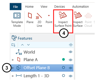
This example uses a 3mm ball Probe to measure the Inspect Surface Point.
- The surface points are about 3mm away from the surface (Offset Plane B).
- The surface points are project on the surface (Offset Plane B), by using the Flip Vector option on the (Offset Plane B).
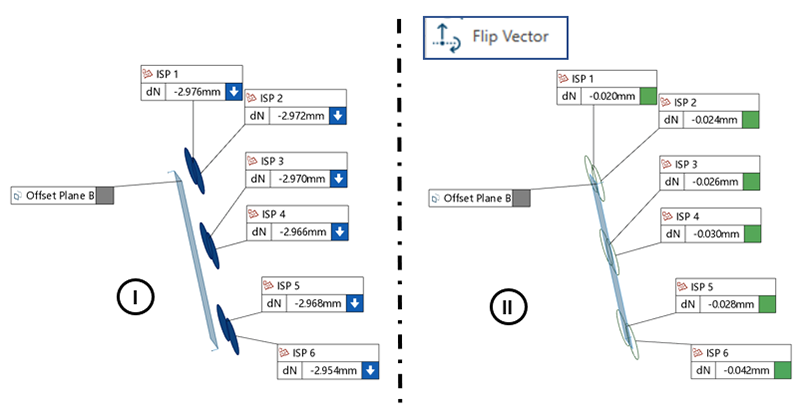
- After this you can create the lengths from each point to Plane A.
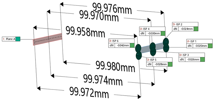
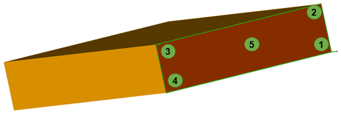
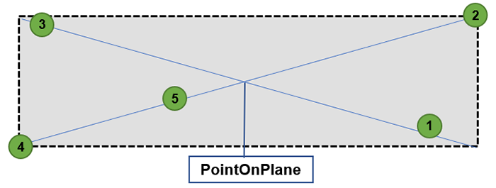
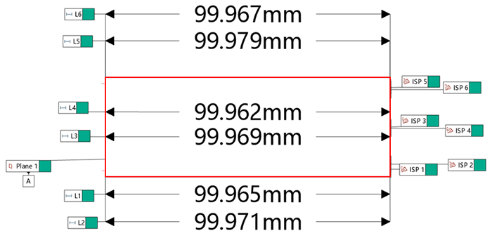
- If you are not using CAD, you can measure all the planes of the gauge block and construct the corner points of Plane A and B as shown below.
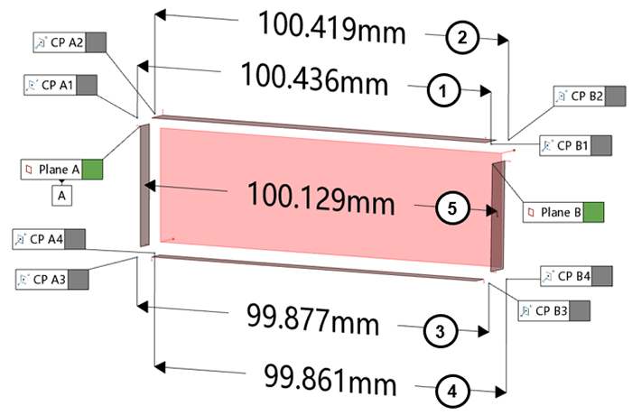
Length’s:
- Length between CP A1 – CP B1.
- Length between CP A2 – CP B2.
- Length between CP A3 – CP B3.
- Length between CP A4 – CP B4.
- Length between Plane A – Plane B.