                     
As-Built As-Built - Revit As-Built - AutoCAD VirtuSurv - VirtuSurv 2018 As-Built - Modeler VirtuSurv - VirtuSurv 2019          
BuildIT BuildIT - Projector BuildIT - Construction BuildIT - Metrology              
CAM2 CAM2 - SmartInspect CAM2 - 2023 CAM2 - 2018 CAM2 - Measure 10 CAM2 - Measure Q CAM2 - Measure X CAM2 - Measure 3/4 CAM2 - AnthroCAM CAM2 - 2019 CAM2 - 2020
CAM2 CAM2 - 2021                  
Cobalt 3D Imager 3D Imager - Cobalt                  
Cobalt Design Cobalt Design - M Cobalt Design - S Cobalt Design - Dual              
Computers Computers - All Computers                  
FARO Aras 360 & CAD Zone FARO CAD Zone - Fire & Insurance FARO CAD Zone - Crime & Crash FARO CAD Zone - CZ Point Cloud FARO CAD Zone - First Look Pro FARO 360 - Reality FARO 360 - HD FARO 360 - Blitz FARO 360 - Genius    
FARO Connect FARO Connect - Connect                  
FARO Zone present4D - present4D                  
FARO Zone 2D FARO Zone 2D - 2018 FARO Zone 2D - 2019 FARO Zone 2D - 2020 FARO Zone 2D - 2021 FARO Zone 2D - 2022 FARO Zone 2D - 2023        
FARO Zone 3D FARO Zone 3D - 2018 FARO Zone 3D - 2019 FARO Zone 3D - 2020 FARO Zone 3D - 2021 FARO Zone 3D - 2022 FARO Zone 3D - 2023 FARO Zone 3D - 2024      
FARO Zone 3D Advanced FARO Zone 3D Advanced - 2018 FARO Zone 3D Advanced - 2019 FARO Zone 3D Advanced - 2020 FARO Zone 3D Advanced - 2021 FARO Zone 3D Advanced - 2022          
FaroArm/ScanArm FaroArm/ScanArm - Quantum S FaroArm/ScanArm - Quantum M FaroArm/ScanArm - Quantum E FaroArm/ScanArm - Edge FaroArm/ScanArm - Fusion FaroArm/ScanArm - Prime FaroArm/ScanArm - Platinum FaroArm/ScanArm - Legacy Quantum FaroArm/ScanArm - Titanium FaroArm/ScanArm - Advantage
FaroArm/ScanArm FaroArm/ScanArm - Digital Template FaroArm/ScanArm - Gage FaroArm/ScanArm - Quantum S Max FaroArm/ScanArm - Quantum M Max FaroArm/ScanArm - Quantum E Max FaroArm/ScanArm - Gage Max        
GeoSLAM Software GeoSLAM Software - Connect GeoSLAM Software - Draw GeoSLAM Software - Hub GeoSLAM Software - Volumes            
GeoSLAM ZEB GeoSLAM ZEB - Horizon GeoSLAM ZEB - Horizon RT GeoSLAM ZEB - Revo GeoSLAM ZEB - Revo RT GeoSLAM ZEB - Go          
Hand Held Scanner 2D Hand Held Scanner - ScanPlan 3D Hand Held Scanner - Freestyle3D 3D Hand Held Scanner - Freestyle3D X 3D Hand Held Scanner - Freestyle3D Objects 3D Hand Held Scanner - Freestyle 2          
Language Quality HT MT AT NT INT - Internal Sales - Internal Resources Sales - Order and Quote Sales - Product Info Sales - Sales Readiness Sales - Training
Language Quality Sales - Product Launch Sales - Promotions CS - Quote to Invoice CS - Phone System CS - New Hire Training CS - General CS - Product Info CS - Licensing CS - Procedures General CS - Procedures Salesforce
Language Quality CS - Procedures Loaner CS - Procedures SAP                
Languages Language - English Language - Japanese Language - German Language - Chinese Language - Spanish Language - Italian Language - Portuguese Language - French Language - Korean  
Laser Projector RayTracer - RayTracer Laser Projector - Tracer M Laser Projector - Tracer SI              
Laser Radar Imaging Laser Radar - VectorRI                  
Laser Scanner 3D Laser Scanner - Focus S 3D Laser Scanner - Focus M 3D Laser Scanner - Focus3D 3D Laser Scanner - Focus3D X 3D Laser Scanner - Focus3D X HDR 3D Laser Scanner - Focus3D S 3D Laser Scanner - Photon 3D Laser Scanner - Focus S Plus 3D Laser Scanner - Swift 3D Laser Scanner - Focus Premium
Laser Scanner 3D Laser Scanner - Focus Core                  
Laser Tracker Laser Tracker - Vantage Laser Tracker - ION Laser Tracker - Vantage S Laser Tracker - Si Laser Tracker - X Laser Tracker - Xi Laser Tracker - Vantage E Laser Tracker - Vantage S6 Laser Tracker - Vantage E6  
Legacy Gage Legacy Gage - Bluetooth Legacy Gage - Plus Legacy Gage - Standard Legacy Gage - Power            
Legacy Software Legacy Software - CAM2 Gage Legacy Software - Gage Software Legacy Software - Insight              
Mobile Scanner Mobile Scanner - Orbis                  
PointSense PointSense - Basic PointSense - Pro PointSense - Building PointSense - Plant PointSense - Heritage PointSense - Revit CAD Plugin - TachyCAD Building CAD Plugin - TachyCAD Archeology CAD Plugin - TachyCAD Interior CAD Plugin - PhoToPlan Basic
PointSense CAD Plugin - PhoToPlan CAD Plugin - PhoToPlan Pro CAD Plugin - PhoToPlan Ultimate CAD Plugin - DisToPlan CAD Plugin - MonuMap CAD Plugin - hylasFM CAD Plugin - VirtuSurv      
RevEng RevEng - RevEng                  
ScanArm ScanArm - Design ScanArm 2.0 ScanArm - Design ScanArm ScanArm - Forensic ScanArm ScanArm - Design ScanArm 2.5C            
SCENE SCENE - Capture and Process SCENE - WebShare Server and 2Go SCENE - WebShare 2Go App SCENE - 2018 SCENE - 7.x SCENE - 6.x SCENE - 5.x SCENE - 4.x SCENE - LT SCENE - 2019
SCENE SCENE - 2go App SCENE - 2020 SCENE - 2021 SCENE - 2022 SCENE - 2023          
Serial FaroArm Serial FaroArm - Silver Serial FaroArm - Gold Serial FaroArm - Bronze              
Sphere FARO Sphere - Sphere                  
Visual Inspect Visual Inspect - App Visual Inspect - CAD Translator                
WebShare WebShare - Enterprise WebShare - WebShare Cloud                

SCENE

2023

2022

2021

2020

2019

FARO® Knowledge Base

Calculating Blood Spatter Origin in SCENE

scene-bty.png

Overview

Use the Forensic Wizard in SCENE 2019 to calculate blood spatter origin.

Associate Image with Scanned Data

  1. Drag and drop the blood spatter image into the Workspace.
  2. In the Import Picture window, chose Virtual scan that may be fitted to the 3D world. Click OK.
    SceneHeight.png
  3. Open a Planar View of the scan
    MeasurePointPlane.png
  4. Create a plane on the surface where the blood spatter is located.
  5. Right-click the image in the Workspace and select Operations > Registration > Place on Surface.  A 3DPictureFit dialog box appears.
    BloodSpatterPictureFit.png
  6. Highlight the plane created in step 4) via the Workspace
  7. In the 3DPictureFit window, click the Use Selection button for the Plane

Associating Points

  1. To begin associating points, click Associate Points in the 3DPictureFit window .
    1. If Associate Points is grayed out, click Done or Apply.  Accept the error messages displayed, and Associate Points should become available.
  2. You will see a split screen with your scan and the photo. Adjust the split screen and move the 3DPictureFit dialog box to view the scan and image comfortably.
    Note: Press CTRL+D to deselect your plane if it is highlighted in yellow.
    BloodSpatterSplit.png
  3. Click a point on the scan and the same point in the image.
  4. Select at least 6 corresponding points between the scan and the image.  For a strong resection, use at least eight (8) corresponding points. 
    • Use CTRL to toggle between selection mode and pan/zoom mode within each view, or use the scroll bars on the sides and bottom of each window to navigate.
    • To delete a pair of points, right-click over the number of the point in the 3DPictureFit dialog box and select Delete pair.
    • To reassign a selection, right-click over the number to reassign in the 3DPictureFit dialog box and select Reassign.
    • Verify that 3D projective it is less than 3mm (1/8”).
  5. When finished, click Done and then click OK.
    BloodSpatterAligned.png

Calculate the Blood Spatter’s Origin

  1. Open a planar view of your blood spatter photo.
  2. Click the Apps icon App button.png and choose Forensic Wizard Forensic Wizard Icon.png.
  3. Click Calculate blood spatter origin.
  4. Click Wizard to create blood drops and click Next.
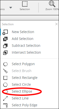
  5. Follow the instructions in the Blood Drop Creation menu using the Select Ellipse tool located in the Selection drop down menu on the Explore tab.
    SelectEllipse.png

Creating Drops

Once you have selected the drop with the ellipse tool, right-click and select Create object > Drop.
BloodSpatterDropEllipse2.png

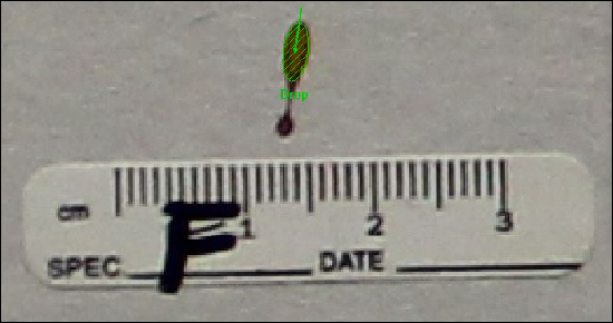
  • When using the ellipse tool, the first point selected should begin at the origin of the blood drop with the second ending at its endpoint.
  • Adjust the size of the ellipse, using the scroll wheel on a mouse, according to the size of the blood spatter.
  • Choose drops with upward directions if possible.
  • Select drops that are highly elliptical in shape. Longer stains are best.
  • Don’t choose odd stains in a cluster as it could be a secondary stain that does not fit the overall pattern.
  • Where possible, choose stains on both sides of the suspected origin.
  • Avoid stains on surfaces that are extremely curved.
  • You may close any Drop Fit menus which pop up. In this menu you can see the drop’s dimensions.
  • Repeat this process for the drops you wish to use for analysis.

Completing Blood Spatter Origin 

  1. Click Next in the Calculate Blood Spatter Origin pop-up window until you get the message stating "Blood spatter trajectories are created or updated.  Origin for trajectories is created or updated." 
  2. Click Cancel. An origin has been created
  3. In the Structure window, expand the Origins folder until you see the origin image file with a red star next to it.
    BloodSpatterOrigin2.png
  4. Right click on the image and chose View > 3D view to see the point of origin in 3D scan data.
    BloodSpatterOrigin.png

Obtaining Dimensions to the Origin Point

An Origins folder will appear in the Structure window. Within the folder an origin point can be identified by the red star icon:

  1. Use Measure objects to measure between planes created and the origin point in the Origins folder
  2. Create other planes to obtain the required dimensions to the origin point.

What to do if a Warning Appears During the Creation of the Spatter Origin

If a message appears stating: or “Warning: The calculated origin is not in a plausible position.  Check the correctness of start and end points for all used trajectories!” use the instructions below:

  1. Click Ok.
  2. Click Cancel to exit the Wizard.
  3. Review the position of the origin point, using measurements or a 3D View of the Workspace.
  4. Create additional drops as needed, or remove drops that were created.
  5. When prompted “Line already exists. Do you want to replace old line?” click Yes all.
  6. When prompted “Origin already exists. Do you want to replace old origin?” click Yes all.
  7. Once the note appears stating “Blood spatter trajectories are created or updated. Origin for trajectories is created or updated” click Cancel.