Laser Scanner Best Practices
Overview
Careful planning and understanding the principles of scanning are essential to capturing accurate and professional scans in an efficient and cost-effective manner. These guidelines will help you deal with common issues that many experience during scanning projects.
Site Sketch
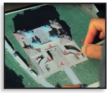
A quick sketch of the scanning site can help save time and determine the optimal scanning locations. It will also help identify additional physical limitations that might impact a scanning project, such as obstructions, power needs, and additional equipment needs. If the project site is an existing outdoor structure, printing a Google Earth or other satellite image is a great way to organize a scanning strategy.
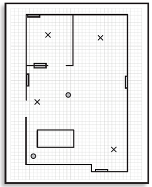
A hand-drawn sketch is also an effective tool.
File Naming
When setting up a larger project on a scanner, it is a good idea to identify areas that can be grouped as scan clusters to make registration easier. You can set project and subproject names in Manage > Projects/Clusters.
Give each scanning project, and folders within the project, names with meaning. For example, a case or job number, client name or number, or street locations. A multi-story building project could have the following file structure:
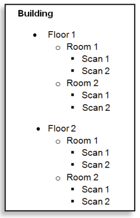
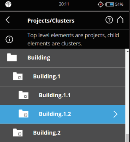
The easiest way to create this file structure on the scanner is to add subprojects and let the scanner automatically name each subproject and each scan.
Equipment Check
- Check the scanner tripod to ensure that all legs lock securely and that the scanner attaches correctly.
- Check the outer casing of the scanner for any signs of damage or distortion.
- Check the scanner mirror for dirt, scratches, cracks, and distortion. Click here for information about cleaning the Laser Scanner mirror.
Artificial Targets
Registration requires unique features in the scan location which can be used to align scans (angular road signs, doors, lamp posts, etc.). Locations, like a flat stretch of road or angular rooms require artificial targets to aid the scan registration process.
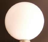
Target spheres can be placed in almost any location and can be scanned from any angle, making them a versatile choice for sites that lack surfaces to which paper targets can be attached. FARO spheres are rigorously produced and ideal for projects with a stricter accuracy threshold.
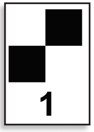
Checkerboard targets can easily be printed, labeled, and resized as needed, but they also must be attached to a flat surface and placed perpendicular to the scanner.
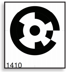
Coded markers function like checkerboards but contain an optical barcode with a unique number. These unique markers help determine the scan location and ease automatic registration. They can be printed after installing SCENE from <Installation Path>\RegistrationMarkers\RegistrationMarkersA4.pdf or downloaded from this page.
Target Placement
Artificial Target Guidelines
- At least three targets are required for registration. (Two, if using sensor data, such as the inclinometer.)
- Arrange targets so that there is a clear line of sight from the scanner to the targets.
- Ensure that each target is visible from more than one scanner position.
- Arrange targets in unique patterns in three dimensions by varying the height and spacing of the targets.
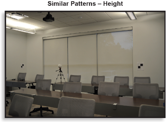
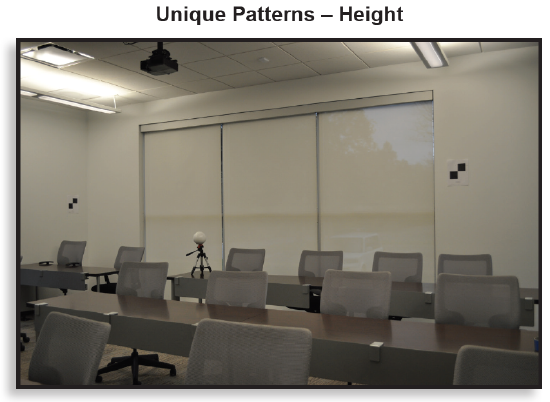
- Do not move the targets during the scanning process.
See Also
Batteries/Extension Cords
Power needs will vary depending on the type of scanning project. Plan appropriately for battery charging time and outlet use as necessary. If the scanner will be plugged into an outlet during a lengthy scanning process, consider using a cord protector to prevent damage from tripping over power cords.
Accuracy Check
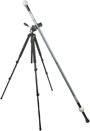
Placing an item with a known length such as a FARO Scale Bar or meter/yard stick in the first scan area is a good way to verify the accuracy of scans after registration is complete. For projects with a higher accuracy threshold, a FARO Scale Bar has a certified length of 1500mm with additional documentation to support scan accuracy.
Additional Scanners
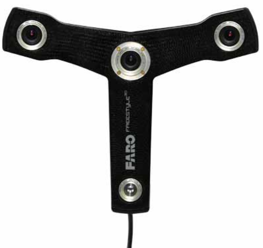
The handheld FARO Freestyle captures point data for smaller objects and spaces. Freestyle data can be registered with Focus data in SCENE.
Number of Scanner Positions
Minimizing scanner positions will reduce scanning time and ensure point data is captured adequately. Use a site sketch to identify optimal scanning locations. Place the scanner in positions where each scan will overlap with another scan. Scan areas should contain unique natural targets to help register the scans. Keep in mind that a full 360° scan may not be necessary every time, depending on the object of interest. Be sure to scan transition areas like doorways to aid registration.
Line of Sight
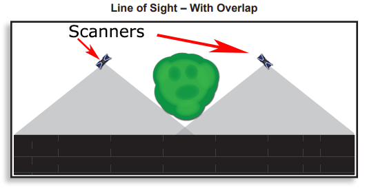
Obstructions such as trees or columns will often require adjusting scanning positions to ensure all scanning data can be captured around the object. When working with multiple scans or scanners, make sure the scan areas overlap beyond the obstruction.
Angle to Object of Interest
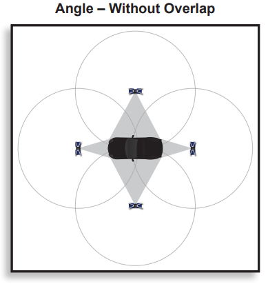
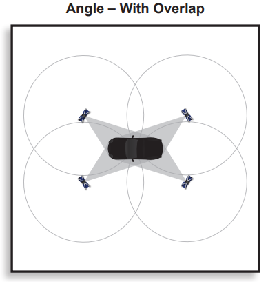
Multiple scans captured from different angles provide the most complete three-dimensional image. Selecting proper angles can reduce the number of required scans. Position the scanner at angles to the object of interest that will give you the best line of sight for capturing the necessary details and ensure that scans contain overlapping areas.
Bisecting
Avoid positioning the scanner so that the start/stop point is on the object of interest or an artificial target. The start/stop line or seam should face the area of least interest.
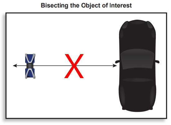
A simple rule of thumb is to make sure you are facing the object of interest when using the scanner touch screen, which is located on the side of the scanner.
Scan Order Matters
Scanning in a logical order will make registration much easier. Circling an object of interest or progressing linearly through a structure will make it easier to keep track of and register scans. The harder it is to follow the scan order on a sketch of the project area, the harder it will be to register the scans later.
Scan Plane
If the scan object of interest is resting on a moving plane, such as a boat on water, it is a good idea to have the scanner on the same plane of movement to prevent tiny movements from affecting measurement data.
ScanPlan and Scan Assist
The FARO handheld 2D scanner, the ScanPlan, allows you to quickly make a map of a building floorplan. With the ScanPlan's Scan Assist mode, it will suggest the best possible locations for positioning your Focus scanner. For more information about using Scan Assist visit this article.
Scan Resolution
Scan resolution refers to the number of data points collected and the distance between those points. Choose a resolution based on the level of detail needed, the distance to the object of interest, and the distance to the targets.
General Resolution Guidelines
- 1/1 or 1/2 - Objects and small areas
- 1/4 or 1/5 - Outdoors and large, indoor spaces
- 1/8 or 1/10 - Indoors and small, outdoor spaces
Scan Quality
Scan quality refers to the number of measurements the scanner makes to confirm point data. Increasing this setting increases scan accuracy but also increases scan time. The quality setting also employs noise reduction, an algorithm that determines if scan point differences are due to object detail or noise.
General Quality Guidelines
- 2x – Optimal conditions (good lighting, good weather) and when time is a concern
- 3x – Indoors or outdoors with overcast conditions
- 4x – Outdoors in sunny conditions when range is needed, or in inclement weather
Horizontal/Vertical
This setting can restrict the scan area of the scanner, allowing for 180° scans or other subsections.
Note: This setting is persistent, so remember to reset it when moving on to the next scan.
Color
If a scan area is extremely dark or time is a factor, turning off color will reduce scan time.
Note: Some surfaces in a raw scan may appear washed out due to the near infrared nature of the scanner and the varying reflection/intensity values. When scans are colorized, these details should be visible.
Exposure Metering
- Even Weighted: Ideal if lighting is relatively uniform, this setting uses light coming from the entire scene and takes less time.
- Horizon Weighted: Best for scenes with bright overhead lighting, the camera uses light from the horizon level.
- Zenith Weighted: Best for scenes where bright lighting comes from eye level or below, the camera uses light information from above.
Predefined Scan Profiles
The fastest way to determine project needs is to use the predefined scan profiles on the scanner.
Newer Models: Focus Core, Focus Premium, Focus Premium Max
| Profile | Use When | Resolution | Quality | Color | Sensors |
|---|---|---|---|---|---|
| Accelerated | Indoors, distance between scanner and object of interest is under 10m | 1/8 | 3X | Off | On |
| Standard | Indoors, distance between scanner and object of interest is over 10m | 1/5 | 3X | Off | On |
| Extended | Outdoor, distance between scanner and object of interest is over 20m | 1/4 | 3X | Off | On |
| Object HD1 | High-resolution scan for nearer objects | 1/2 | 4X | On | On |
| Flash2 | Indoors, distance between scanner and object of interest is under 10m | 1/43 | 2x | On | Off |
Note1: The Object HD profile uses the internal camera with 8MPx resolution (only the High Resolution setting uses 13MPx). It also uses the Near Distance Range setting for closer objects.
Note2: The Flash profile is only available when using the FARO Stream app and with a valid license. Flash uses the PanoCam accessory with a Ricoh Theta Z1 and an rough, less accurate inclinometer reading.
Note3: 1/4 vertical resolution and 3 rpm (10 s) horizontal resolution
General information:
It is possible to customize and clone the above-mentioned predefined profiles (not valid for Flash) or create new profiles. Please use customized profiles for environment specific scanning. Stream profiles are not synchronized with the Focus scanner to avoid conflicts between multiple devices.
Legacy Models: FocusS, FocusS Plus, FocusM
| Profile | Use When | Resolution | Quality | Color | Sensors |
|---|---|---|---|---|---|
| Indoor ...10m | Indoors, distance between scanner and object of interest is under 10m | 1/8 | 3X | On | On |
| Indoor 10m... | Indoors, distance between scanner and object of interest is over 10m | 1/5 | 4X | On | On |
| Indoor HDR | Indoors, distance between scanner and object is under 20m with HDR quality | 1/5 | 4X | On | On |
| Outdoor ...20m | Outdoor, distance between scanner and object of interest is under 20m | 1/5 | 4X | On | On |
| Outdoor 20m... | Outdoor, distance between scanner and object of interest is over 20m | 1/4 | 4X | On | On |
| Outdoor HDR | Outdoor, distance between scanner and object of interest is over 20m with HDR quality | 1/4 | 4X | On | On |
| Preview | Quick, low-res scan | 1/16 | 4X | Off | Off |
| Object HD | High-res scan | 1/2 | 6X | On | On |
| Outdoor: Far Distances | Distance between scanner and object of interest is over 20m, and measurement accuracy of objects closer to scanner isn't necessary. | 1/4 | 4X | On | On |
Predefined scan profiles can be altered as needed, and custom scan profiles can be added for individual needs.
Inclinometer
Try to position the scanner so that its inclination is between +/-5°. An inclination warning icon in the status bar ![]() is only visible when the current inclination of the scanner is above 2° (the icon becomes yellow) or the icon becomes red if the scanner is tilted more than 5°.
is only visible when the current inclination of the scanner is above 2° (the icon becomes yellow) or the icon becomes red if the scanner is tilted more than 5°.
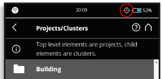
You can level your inclinometer by selecting Home > Parameters > Select Sensors. The view displays a bulls eye bubble level inclinometer as it would appear if mounted on top of the scanner.
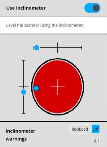
You can enable or disable the automatic use of the inclination measurement of the inclinometer for the scan registration in SCENE. However, regardless of your setting, the data of this sensor is always measured and attached to each scan. If the use of the inclinometer data is switched ON, it will automatically be used to register the scans in SCENE; if it is switched off, the data will be ignored.
The inclinometer should be switched off, if you are scanning upside down.
Note: If you are scanning outdoors or in an area with unstable surfaces, double check the inclinometer bubble before moving to the next scan. Select Manage > Sensors > Inclinometer. If the inclinometer is in the Red Zone then re-level the scanner, check the tripod legs are secure and stable, then scan again.
Inclement Weather
- Rain - Decrease resolution to reduce the number of droplets scanned, and increase quality to confirm measurement data.
- Fog - Increase resolution to 1/4 or 1/3 and use 3x, 4x quality.
- High Winds - Lower tripod height, and use 8-to-10 pound sandbags to steady the tripod. Caution: Do not leave scanner unattended in high winds.
- Heat - If operating in strong direct sunlight or temperatures over 40°C (104°F), a heat protection cover can help protect the scanner and extend operation time.
Troublesome Surfaces
- Bright – Bright surfaces can cause an increase in scan noise and loss of measurement data. Increasing scan quality will help reduce the impact of these surfaces. In more intense situations, try covering the surface with masking tape or painter's tape.
- Reflective – Mirrors and other highly reflective surfaces can make scanning challenging. Covering these surfaces with brown paper or tape can minimize their impact.
- Glass – Measuring through glass surfaces will not produce repeatable or accurate results. Unless the glass surface has very specific coatings, back reflections can occur and affect the radial measurements. Even if the glass surface does have proper coatings to prevent or minimize this, the glass has a different index of refraction than the air the beam is traveling through. This index of refraction change can result in an error in the radial distance measurement and will also result in the beam “bending” or no longer traveling a straight path from the tracker to the target. This bending of the beam will affect the measurements from the scanner. The nature of the bend will also change as the angle the beam enters the glass window changes, resulting in a loss of both accuracy and repeatability.
- Water – Water refracts light too much to return a reliable scan result and should be avoided.
- Extremely Hot Surfaces – FARO scanners operate in infrared light. So, beyond the temperature of the target, what matters most is the luminance, or how much light within infrared spectrum it will emit. All items emit IR, and the amount of IR they emit increases as its temperature increases. Extremely hot items (in excess of several hundred degrees Celsius) will tend to emit more IR than they will reflect. At these extreme temperatures it's unlikely that all the laser power emitted from the scanner will reflect and return. This condition can result in missing and inaccurate scan data. In general we don’t recommend to scan any objects that are hotter than 500 °C, as the results are not predictable.
On-Site Registration
Legacy Models: FocusS, FocusS Plus, FocusM
On-site registration enables the scan data, whether it be from a single scan or multiple scans in process simultaneously, to be wirelessly transmitted directly to an on-site PC and automatically aligned. .
New Models: Focus Core, Focus Premium, Focus Premium Max
It is recommended to use the FARO Stream App (available in the Google and Apple stores) for On-Site registration, the Stream will automatically register the new captured scans. Stream uses an automatic top view and cloud-to-cloud based registration. This automatic registration is performed automatically after each scan is completed. It’s also possible to perform manual registration and add scan connections in Stream which can be used for fine registration in SCENE as a final processing step.
For more information see the Stream manual, chapter “Focus Scan Registration”.
Scanner Safety
- CAUTION: Do not leave the scanner unattended.
- Limit traffic in the scan area as much as possible.
- Make the scanner more noticeable by placing painter's tape along the tripod legs, or wrapping them in swimming noodles that have been trimmed to the correct size.
- Use cord protectors to cover the power cord, if it is attached to the scanner.
- When moving the scanner on a tripod, always have one hand on the scanner.
- For unstable ground (such as sand, loose dirt, or industrial grating), try using vibration suppression pads, inserting tripod legs into tennis balls, or placing the legs on top of old compact discs or furniture sliders.
PanoCam
The PanoCam accessory expedites the scanning process by capturing colorized 360° photos in a second.
For all V8 and V9 Focus scanners:
| Model | High Dynamic Range (HDR) |
|---|---|
| Focus V8 legacy: FocusS, FocusS Plus, FocusM | Not available |
| Focus V9: Focus Core, Focus Premium, Focus Premium Max | Optional setting |
General information:
- Use the FARO PanoCam mount (FARO item ACCS-0016) to attach the panoramic camera to the Focus scanner. Only applicable for a Ricoh Theta Z1 camera. Use the latest Focus and Ricoh Theta Z1 camera firmware (see https://support.theta360.com).
- CAUTION! During assembly of the Ricoh Theta Z1 and the PanoCam mount do not over-tighten the camera screw. Damage to the camera or mount could result. It recommended to always use the same force and method to tighten the camera screw. More information and details can be found in the Focus User Manual.
- To achieve best scan colorization results you should perform a PanoCam calibration scan after you assembled the PanoCam mount and the Ricoh Theta Z1. For processing of PanoCam scans in Sphere XG it is currently required to capture a Panocam calibration scan in each project before upload.
- It is recommended to clean the connector contacts of the PanoCam Mount and Focus scanner from time to time. Use a cotton swab and isopropyl alcohol.
Storage
For all V8 and V9 Focus scanners:
| Model | Solid State Drive (SSD) |
|---|---|
| Focus V8 legacy: FocusS, FocusS Plus, FocusM | Not available, only SD card |
| Focus V9: Focus Core, Focus Premium, Focus Premium Max | Operation with integrated SSD or SD card |
General information:
Scan projects are stored on the SSD or SD card depending on the settings in Storage Management. Projects stored on the SSD can be exported to the SD card. It is highly recommended to use the integrated SSD. Using the SD card and setting Automatic SD Card Synchronization will increase your scan capture time. The setting can be reviewed under Manage > Storage Management.
NOTICE: All scans in a project must be saved on the same storage media. Do not switch between Internal (SSD) and SD card storage during a scan project.

