                     
As-Built As-Built - Revit As-Built - AutoCAD VirtuSurv - VirtuSurv 2018 As-Built - Modeler VirtuSurv - VirtuSurv 2019          
BuildIT BuildIT - Projector BuildIT - Construction BuildIT - Metrology              
CAM2 CAM2 - SmartInspect CAM2 - 2023 CAM2 - 2018 CAM2 - Measure 10 CAM2 - Measure Q CAM2 - Measure X CAM2 - Measure 3/4 CAM2 - AnthroCAM CAM2 - 2019 CAM2 - 2020
CAM2 CAM2 - 2021                  
Cobalt 3D Imager 3D Imager - Cobalt                  
Cobalt Design Cobalt Design - M Cobalt Design - S Cobalt Design - Dual              
Computers Computers - All Computers                  
FARO Aras 360 & CAD Zone FARO CAD Zone - Fire & Insurance FARO CAD Zone - Crime & Crash FARO CAD Zone - CZ Point Cloud FARO CAD Zone - First Look Pro FARO 360 - Reality FARO 360 - HD FARO 360 - Blitz FARO 360 - Genius    
FARO Connect FARO Connect - Connect                  
FARO Zone present4D - present4D                  
FARO Zone 2D FARO Zone 2D - 2018 FARO Zone 2D - 2019 FARO Zone 2D - 2020 FARO Zone 2D - 2021 FARO Zone 2D - 2022 FARO Zone 2D - 2023        
FARO Zone 3D FARO Zone 3D - 2018 FARO Zone 3D - 2019 FARO Zone 3D - 2020 FARO Zone 3D - 2021 FARO Zone 3D - 2022 FARO Zone 3D - 2023 FARO Zone 3D - 2024      
FARO Zone 3D Advanced FARO Zone 3D Advanced - 2018 FARO Zone 3D Advanced - 2019 FARO Zone 3D Advanced - 2020 FARO Zone 3D Advanced - 2021 FARO Zone 3D Advanced - 2022          
FaroArm/ScanArm FaroArm/ScanArm - Quantum S FaroArm/ScanArm - Quantum M FaroArm/ScanArm - Quantum E FaroArm/ScanArm - Edge FaroArm/ScanArm - Fusion FaroArm/ScanArm - Prime FaroArm/ScanArm - Platinum FaroArm/ScanArm - Legacy Quantum FaroArm/ScanArm - Titanium FaroArm/ScanArm - Advantage
FaroArm/ScanArm FaroArm/ScanArm - Digital Template FaroArm/ScanArm - Gage FaroArm/ScanArm - Quantum S Max FaroArm/ScanArm - Quantum M Max FaroArm/ScanArm - Quantum E Max FaroArm/ScanArm - Gage Max        
GeoSLAM Software GeoSLAM Software - Connect GeoSLAM Software - Draw GeoSLAM Software - Hub GeoSLAM Software - Volumes            
GeoSLAM ZEB GeoSLAM ZEB - Horizon GeoSLAM ZEB - Horizon RT GeoSLAM ZEB - Revo GeoSLAM ZEB - Revo RT GeoSLAM ZEB - Go          
Hand Held Scanner 2D Hand Held Scanner - ScanPlan 3D Hand Held Scanner - Freestyle3D 3D Hand Held Scanner - Freestyle3D X 3D Hand Held Scanner - Freestyle3D Objects 3D Hand Held Scanner - Freestyle 2          
Language Quality HT MT AT NT INT - Internal Sales - Internal Resources Sales - Order and Quote Sales - Product Info Sales - Sales Readiness Sales - Training
Language Quality Sales - Product Launch Sales - Promotions CS - Quote to Invoice CS - Phone System CS - New Hire Training CS - General CS - Product Info CS - Licensing CS - Procedures General CS - Procedures Salesforce
Language Quality CS - Procedures Loaner CS - Procedures SAP                
Languages Language - English Language - Japanese Language - German Language - Chinese Language - Spanish Language - Italian Language - Portuguese Language - French Language - Korean  
Laser Projector RayTracer - RayTracer Laser Projector - Tracer M Laser Projector - Tracer SI              
Laser Radar Imaging Laser Radar - VectorRI                  
Laser Scanner 3D Laser Scanner - Focus S 3D Laser Scanner - Focus M 3D Laser Scanner - Focus3D 3D Laser Scanner - Focus3D X 3D Laser Scanner - Focus3D X HDR 3D Laser Scanner - Focus3D S 3D Laser Scanner - Photon 3D Laser Scanner - Focus S Plus 3D Laser Scanner - Swift 3D Laser Scanner - Focus Premium
Laser Scanner 3D Laser Scanner - Focus Core                  
Laser Tracker Laser Tracker - Vantage Laser Tracker - ION Laser Tracker - Vantage S Laser Tracker - Si Laser Tracker - X Laser Tracker - Xi Laser Tracker - Vantage E Laser Tracker - Vantage S6 Laser Tracker - Vantage E6  
Legacy Gage Legacy Gage - Bluetooth Legacy Gage - Plus Legacy Gage - Standard Legacy Gage - Power            
Legacy Software Legacy Software - CAM2 Gage Legacy Software - Gage Software Legacy Software - Insight              
Mobile Scanner Mobile Scanner - Orbis                  
PointSense PointSense - Basic PointSense - Pro PointSense - Building PointSense - Plant PointSense - Heritage PointSense - Revit CAD Plugin - TachyCAD Building CAD Plugin - TachyCAD Archeology CAD Plugin - TachyCAD Interior CAD Plugin - PhoToPlan Basic
PointSense CAD Plugin - PhoToPlan CAD Plugin - PhoToPlan Pro CAD Plugin - PhoToPlan Ultimate CAD Plugin - DisToPlan CAD Plugin - MonuMap CAD Plugin - hylasFM CAD Plugin - VirtuSurv      
RevEng RevEng - RevEng                  
ScanArm ScanArm - Design ScanArm 2.0 ScanArm - Design ScanArm ScanArm - Forensic ScanArm ScanArm - Design ScanArm 2.5C            
SCENE SCENE - Capture and Process SCENE - WebShare Server and 2Go SCENE - WebShare 2Go App SCENE - 2018 SCENE - 7.x SCENE - 6.x SCENE - 5.x SCENE - 4.x SCENE - LT SCENE - 2019
SCENE SCENE - 2go App SCENE - 2020 SCENE - 2021 SCENE - 2022 SCENE - 2023          
Serial FaroArm Serial FaroArm - Silver Serial FaroArm - Gold Serial FaroArm - Bronze              
Sphere FARO Sphere - Sphere                  
Visual Inspect Visual Inspect - App Visual Inspect - CAD Translator                
WebShare WebShare - Enterprise WebShare - WebShare Cloud                

BuildIT

Metrology

FARO® Knowledge Base

Characterizing Tooling Points Using BuildIT Bundling Registration

BuildIT-bty-temp.png

Overview

BuildIT’s “Bundling Registration” command allows registering a network of devices which are measuring common points.

This registration allows creating “bundling points” that combine measurements of the same targets, taken from multiple viewpoints.

Highlight Video:


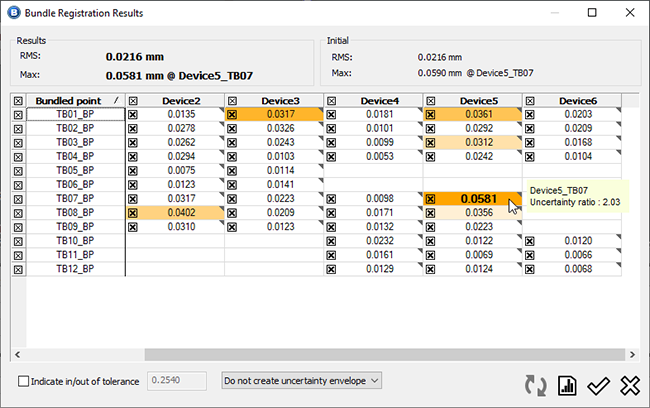
The uncertainty ratio of each point is displayed, and outliers are flagged. The command allows multiple scenario simulations to be run before accepting an alignment.

Bundling-UncertaintyResults.png


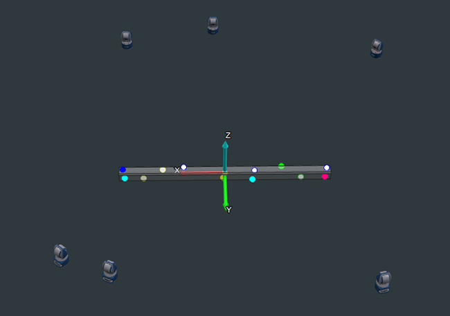
The uncertainty envelope of measurements and resulting bundling points can be visualized in 3D view.

Bundling-UncertaintyEnvelope_3d.png


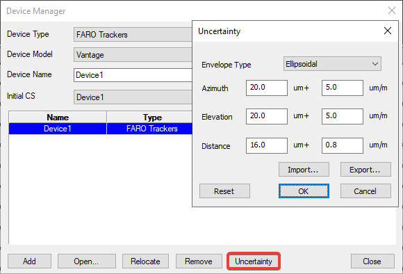
Default values are taken from the device’s datasheet. However, the uncertainty of each device can be fine-tuned based on calibration report values via the Device Manager:

BIT Bundling-Device_Manager_Uncertainty.png
 

Benefit

Combining measurements taken from multiple viewpoints allow reducing the uncertainty on the location of the resulting points. Flagging and ignoring outliers grants user full control over the quality of the output.

Bundling-Fixture.pngTypical Use Case

The Bundling Registration command is typically used for characterizing the actual location of tooling points on a jig or on a fixture. Those are used for future alignments when performing the assembly or verification of that jig or fixture using a laser tracker.

Finely characterized points allow obtaining a consistent alignment to the part regardless of which targets are being measured on subsequent inspections.

Another benefit of having a finely characterized set of points is that it allows computing the scale at the moment of computing the alignment, eliminating the need for recording the actual temperature of the part and applying this scaling manually based on the part material - thus reducing the risks of error.

Workflow

  • When characterizing tooling or equipment, allow the part to soak in the environment so that it attains a stable temperature.
  • Repeat the following steps from multiple device locations:
    • Add a new device (“Device: New” or “Device: Relocate”).
    • Set the device’s scaling based on the jig’s material and temperature (“Align: Set Scaling”)
    • Measure the tooling points which are visible from this position (“Inspect: Point”)
  • Once the tool has been measured from enough positions, run the bundling registration command (“Align: Bundling Registration”). This creates Actual points labeled with the “_BP” suffix
  • Convert those Bundling Points to Nominal (“Edit: Change Type”). These should be saved in the model as the actual position of the tooling points
    • Those points' coordinates are often stamped on the jig or fixture to serve as a reference in the future

Best-practices

Keep in mind that for a laser tracker:

  • Uncertainty envelope is thinner along the radial direction. Positions should be as spread out as possible around the part
  • Uncertainty envelope grow linearly with the distance from the tracker. Points should be measured from as near as possible
  • Points with a high uncertainty ratio generally indicate that at least one measurement was not performed properly (dirt in nest, probe not properly seated, etc.). We recommend removing the worse point and recomputing the alignment. Repeat as necessary.
    Bundling-UncertaintyPoints.png