Creating a GDT Parallelism Call-out in CAM2
Overview
How to apply a GDT parallelism call-out to a feature.
Download a PDF of this article:
Preparation
- Create the datum features as detailed in the following articles:
- Measure the features that require the GDT call-out
Creating the GDT Call-out
- Select the GDT tab
- Highlight the required feature in the Feature panel
- From the ribbon select Parallelism
The GDT panel will open in the lower LH corner of the UI

Note: If the GDT icon is ‘greyed-out’ this details that the selected feature does not support this call-out.
- Within the GDT panel:
- Click into the tolerance, and enter the required value
- Select the required datum

The call-out will be calculated and the result will be shown in the GDT label displayed in the 3D viewer.

Note: To display results in the GDT label select via View > GDT Label > Level of Detail

Copying GDT Call-outs to Other features
This allows multiple features of the same type to have the same call-out applied
- Apply the call-out to the first feature
- Highlight the first feature
- Right click and select Copy Tolerances
- Multi-select other features
- Right click and select Paste Tolerances
- Message ‘Do you also want to paste the GDT tolerances?’, select Yes
The GDT call-out will be applied to the selected features, and the GDT label will be displayed.
How it’s Calculated
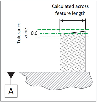
Parallelism measures the condition of a plane or axis that is equal in distance at all points from the datum plane or axis.
A tolerance zone is applied, that is perfectly parallel to the datum feature. The measured surface or axis of the feature, across its full length, must remain within this zone to be deemed as acceptable.
Note: When measuring the feature to be checked, the length of the feature is critical to this calculation. Therefore the full length of the feature must be measured.
| This on a drawing... | Means this when calculated... |
|---|---|
 |
 |
See Also
Keywords:
GD&T, Help Sheet, GDT004

