                     
As-Built As-Built - Revit As-Built - AutoCAD VirtuSurv - VirtuSurv 2018 As-Built - Modeler VirtuSurv - VirtuSurv 2019          
BuildIT BuildIT - Projector BuildIT - Construction BuildIT - Metrology              
CAM2 CAM2 - SmartInspect CAM2 - 2023 CAM2 - 2018 CAM2 - Measure 10 CAM2 - Measure Q CAM2 - Measure X CAM2 - Measure 3/4 CAM2 - AnthroCAM CAM2 - 2019 CAM2 - 2020
CAM2 CAM2 - 2021                  
Cobalt 3D Imager 3D Imager - Cobalt                  
Cobalt Design Cobalt Design - M Cobalt Design - S Cobalt Design - Dual              
Computers Computers - All Computers                  
FARO Aras 360 & CAD Zone FARO CAD Zone - Fire & Insurance FARO CAD Zone - Crime & Crash FARO CAD Zone - CZ Point Cloud FARO CAD Zone - First Look Pro FARO 360 - Reality FARO 360 - HD FARO 360 - Blitz FARO 360 - Genius    
FARO Connect FARO Connect - Connect                  
FARO Zone present4D - present4D                  
FARO Zone 2D FARO Zone 2D - 2018 FARO Zone 2D - 2019 FARO Zone 2D - 2020 FARO Zone 2D - 2021 FARO Zone 2D - 2022 FARO Zone 2D - 2023        
FARO Zone 3D FARO Zone 3D - 2018 FARO Zone 3D - 2019 FARO Zone 3D - 2020 FARO Zone 3D - 2021 FARO Zone 3D - 2022 FARO Zone 3D - 2023 FARO Zone 3D - 2024      
FARO Zone 3D Advanced FARO Zone 3D Advanced - 2018 FARO Zone 3D Advanced - 2019 FARO Zone 3D Advanced - 2020 FARO Zone 3D Advanced - 2021 FARO Zone 3D Advanced - 2022          
FaroArm/ScanArm FaroArm/ScanArm - Quantum S FaroArm/ScanArm - Quantum M FaroArm/ScanArm - Quantum E FaroArm/ScanArm - Edge FaroArm/ScanArm - Fusion FaroArm/ScanArm - Prime FaroArm/ScanArm - Platinum FaroArm/ScanArm - Legacy Quantum FaroArm/ScanArm - Titanium FaroArm/ScanArm - Advantage
FaroArm/ScanArm FaroArm/ScanArm - Digital Template FaroArm/ScanArm - Gage FaroArm/ScanArm - Quantum S Max FaroArm/ScanArm - Quantum M Max FaroArm/ScanArm - Quantum E Max FaroArm/ScanArm - Gage Max        
GeoSLAM Software GeoSLAM Software - Connect GeoSLAM Software - Draw GeoSLAM Software - Hub GeoSLAM Software - Volumes            
GeoSLAM ZEB GeoSLAM ZEB - Horizon GeoSLAM ZEB - Horizon RT GeoSLAM ZEB - Revo GeoSLAM ZEB - Revo RT GeoSLAM ZEB - Go          
Hand Held Scanner 2D Hand Held Scanner - ScanPlan 3D Hand Held Scanner - Freestyle3D 3D Hand Held Scanner - Freestyle3D X 3D Hand Held Scanner - Freestyle3D Objects 3D Hand Held Scanner - Freestyle 2          
Language Quality HT MT AT NT INT - Internal Sales - Internal Resources Sales - Order and Quote Sales - Product Info Sales - Sales Readiness Sales - Training
Language Quality Sales - Product Launch Sales - Promotions CS - Quote to Invoice CS - Phone System CS - New Hire Training CS - General CS - Product Info CS - Licensing CS - Procedures General CS - Procedures Salesforce
Language Quality CS - Procedures Loaner CS - Procedures SAP                
Languages Language - English Language - Japanese Language - German Language - Chinese Language - Spanish Language - Italian Language - Portuguese Language - French Language - Korean  
Laser Projector RayTracer - RayTracer Laser Projector - Tracer M Laser Projector - Tracer SI              
Laser Radar Imaging Laser Radar - VectorRI                  
Laser Scanner 3D Laser Scanner - Focus S 3D Laser Scanner - Focus M 3D Laser Scanner - Focus3D 3D Laser Scanner - Focus3D X 3D Laser Scanner - Focus3D X HDR 3D Laser Scanner - Focus3D S 3D Laser Scanner - Photon 3D Laser Scanner - Focus S Plus 3D Laser Scanner - Swift 3D Laser Scanner - Focus Premium
Laser Scanner 3D Laser Scanner - Focus Core                  
Laser Tracker Laser Tracker - Vantage Laser Tracker - ION Laser Tracker - Vantage S Laser Tracker - Si Laser Tracker - X Laser Tracker - Xi Laser Tracker - Vantage E Laser Tracker - Vantage S6 Laser Tracker - Vantage E6  
Legacy Gage Legacy Gage - Bluetooth Legacy Gage - Plus Legacy Gage - Standard Legacy Gage - Power            
Legacy Software Legacy Software - CAM2 Gage Legacy Software - Gage Software Legacy Software - Insight              
Mobile Scanner Mobile Scanner - Orbis                  
PointSense PointSense - Basic PointSense - Pro PointSense - Building PointSense - Plant PointSense - Heritage PointSense - Revit CAD Plugin - TachyCAD Building CAD Plugin - TachyCAD Archeology CAD Plugin - TachyCAD Interior CAD Plugin - PhoToPlan Basic
PointSense CAD Plugin - PhoToPlan CAD Plugin - PhoToPlan Pro CAD Plugin - PhoToPlan Ultimate CAD Plugin - DisToPlan CAD Plugin - MonuMap CAD Plugin - hylasFM CAD Plugin - VirtuSurv      
RevEng RevEng - RevEng                  
ScanArm ScanArm - Design ScanArm 2.0 ScanArm - Design ScanArm ScanArm - Forensic ScanArm ScanArm - Design ScanArm 2.5C            
SCENE SCENE - Capture and Process SCENE - WebShare Server and 2Go SCENE - WebShare 2Go App SCENE - 2018 SCENE - 7.x SCENE - 6.x SCENE - 5.x SCENE - 4.x SCENE - LT SCENE - 2019
SCENE SCENE - 2go App SCENE - 2020 SCENE - 2021 SCENE - 2022 SCENE - 2023          
Serial FaroArm Serial FaroArm - Silver Serial FaroArm - Gold Serial FaroArm - Bronze              
Sphere FARO Sphere - Sphere                  
Visual Inspect Visual Inspect - App Visual Inspect - CAD Translator                
WebShare WebShare - Enterprise WebShare - WebShare Cloud                

Laser Tracker

Vantage S

Vantage S6

Vantage E

Vantage E6

Vantage

ION

Si

X

Xi

FARO® Knowledge Base

Mounting Options for the Laser Tracker

Laser Tracker Vantage Icon

Mounting the Laser Tracker

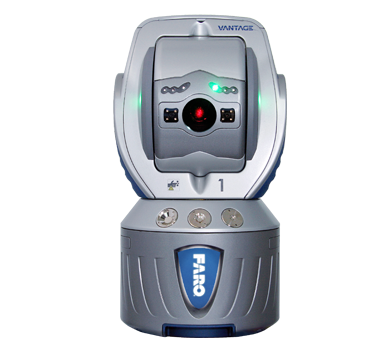
You can mount the Laser Tracker in any orientation without affecting the accuracy of its measurements. There are three mounting options for the Laser Tracker:The FARO®

  1. Mount the Laser Tracker in the vertical position on an instrument stand or a trivet through the use of its mounting mandrel. Screw the mandrel onto to the instrument stand using a 3.5”-8 UNC-2B thread. 
     
  2. The mandrel receptacle at the bottom of the Laser Tracker also has a bolt pattern that can also be used for mounting. This bolt pattern consists of four (4) 0.25”-20 UNC-2B holes spaced equally apart at 90 degree intervals. The bolt pattern forms a circle diameter of 3.5”. See the next section for more information.
     
  3. The receptacle at the bottom of the Laser Tracker is threaded into the bottom of the Laser Tracker. This receptacle can be removed to expose the same 3.5”-8 UNC-2B thread as the mandrel. Removing the mandrel receptacle allows the Laser Tracker to be threaded directly onto an instrument stand or stand extension tube.

Use Bolt Hole Pattern Beneath Tracker for Mounting  

The bottom of the Laser Tracker has a bolt hole pattern that can be used to mount the tracker to a fixture or mount instead of using the mandrel.

For the Vantage Tracker, this bolt pattern consists of four (4) 0.25”-20 UNC-2B holes spaced equally apart at 90 degree intervals. The bolt pattern forms a circle diameter of 3.125”.

For the ION / X/ Xi and Si Trackers, this bolt pattern consists of eight (8) 0.25"-20 UNC-2B holes spaced equally apart at 45 degree intervals. The bolt pattern forms a circle diameter of 3.126".

CAUTION:  The mandrel mount is designed to hold the Laser Tracker in only the upright vertical position or in the horizontal position. To mount the Laser Tracker at any angle past horizontal, bolt it directly into a mounting fixture.

Orientation Options: Upright, Horizontal, Sideways, or Upside Down

The FARO Laser Tracker can be mounted upright, horizontal or sideways, and upside down. Regardless of how you mount the Tracker, a stable, vibration-free mount plays a critical role in measurement accuracy. The Tracker technical specifications for accuracy do not change. The operator should follow best practices for measurement and make sure that the Tracker in its mounted position is properly compensated. This article discusses options for mounting in all orientations.  

Upright

For upright mounting you can use the mandrel or your own custom mount. For details about the standard upright mounting, see the User Manual for your Tracker model. If you want a permanent mounting for an upright Tracker, you can use similar techniques as those discussed here for other mounting orientations. 

Horizontal or Sideways

For horizontal or sideways mounting, you can use the expanding mandrel or your own custom mount.

The Laser Tracker Accessories Manual has a sideways mount that is ideal for this purpose. The FARO sideways mount has a counterbalance to offset the Tracker's weight. However, the counterbalance takes up room behind the Tracker and can prevent it from being mounted in tight areas.

Tracker mounted sideways on a custom mountUser-added image

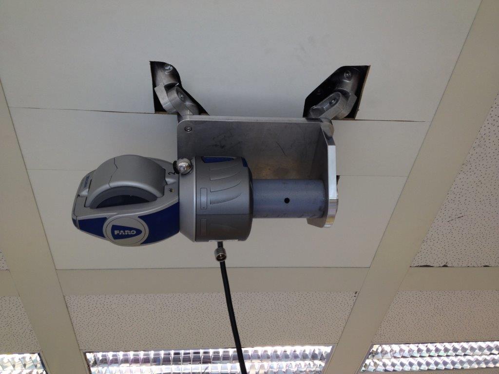
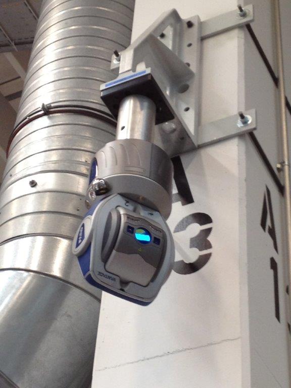
Below is a picture of the tracker mounted on a machine tool and the optional side mount listed in the Laser Tracker Accessories Manual.


User-added image

ion_sidemount.PNG

Side Mount (ION Model)
Part #
: 099-01138

vantage_sidemount.PNG

Side Mount (Vantage Model)
Part #:
C-ACC-07885-000 

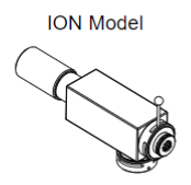
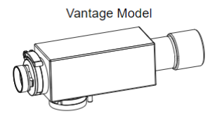
Mounts the Laser Tracker sideways on a heavy duty instrument stand.

The mount includes: mount housing, counterweight, mandrel receptacle and two mandrels.


Upside Down

For upside down mounting, do not use the mandrel. When mounting the Tracker past the horizontal sideways position, the circular bolt pattern on the bottom of the Tracker's mandrel receptacle should be used to bolt the Tracker to the mount. This circular bolt pattern consists of four 0.25”-20 UNC-2B holes spaced equally apart at 90° intervals. For the Vantage Laser Tracker, the bolt pattern’s diameter is 3.5” For the ION, X, Xi and SI Laser Tracker, the bolt pattern’s diameter is 3.125”.

Alternatively, the Tracker’s mandrel receptacle can be removed to expose the 3.5” diameter thread pattern. This thread pattern is identical to the pattern on the bottom of the mandrel and allows the Tracker to be threaded directly onto a mount.

Tracker mounted upside down on a rigid post

Dimensions and Mounting Instructions for the 1.5 Inch SMR Permanent Reference Mount

Part #C-ACC-05430-00

The 1.5" Spherically Mounted Retroreflector (SMR) Permanent Reference Mount is designed for mounting a permanent reference to a surface to securely hold a 1.5" SMR. This mount is used for reference only and is not intended for critical offsets or concentricity.  It has a cover to keep dust and dirt out of it and has laser etched dimensions to identify the target holder for component management.

It can be permanently secured using 1/4" bolts, through two counter bored holes in the base. Two 15/64” guide holes can be used as drill guides for the placement of dowels. After drilling 15/64ths holes into the substrate, use 1/4" reamer and then insert dowels to permanently mount the nest in this location.

  • Mounting holes:  0.266" diameter, counterbored to 0.438" diameter.  0.250" deep placed on 1.750" centers
  • Doweling holes: 0.235" diameter through placed on 1.750" centers

Center Location of SMR when using 1.5 inch Permanent Reference Mount

With the 1.5 inch SMR Permanent Reference Mount, the center of the SMR sits 1.25 inches from the bottom of the mounting surface.
The nest itself is 0.75 inches high.